My 1976 Jeep CJ-5
Find me on JeepForum
Lighting Upgrade—Approach and Auxiliary Fuse Block
After spending a few evenings driving around after dark it became clear to me that I needed to enhance the stock lighting on "Bob" sooner rather than later. After some searching on the Jeep forums (JeepForum.com and CJOffroad.com) and a few other project sites (Ralph Hassel's Project CJ-7 pages and Glenn Bontly's We Be Jeepin'! pages in particular) I decided that the recommendation to install relays in control of the lights, while continuing to use the existing wiring to control the relays, was the way to go. Further research on the Daniel Stern Lighting Consultants site sealed the deal.
My first action was to contact Daniel Stern directly and he most helpfully provided some advice and guidance on reworking the existing lighting setup for the Jeep. My approach includes replacing the existing cheapie Wagner headlamps with much more powerful Cibié 7" H4 reflectors with Osram 70/65w H4 bulbs. I'm also bumping up the plug-in bulbs for the front turn signal indicators, perimeter running lights, brake and back-up lights with newer, brighter bulbs (no wiring mods required for this second part).
With this approach the more powerful headlamps are further enhanced using a relay-based setup with new, heavier gauge wiring providing power to the headlamps for brighter lights while continuing to use the existing switches and skimpy factory wiring for overall control. See Mr Stern's Relays: Why and How to Upgrade your Headlamp Circuit pages for the technical details as to why.
In order to visualize how all of this was going to work I made a wiring diagram. You'll note the presence of an auxiliary fuse block which seemed like a good idea - to support future expansion (fog lights, decent stereo, etc.). A number of folks recommend the Painless Performance products so that's what I'm went with. Though the Daniel Stern relay kits come with fuses and all that good stuff I figure I'd run things right into the auxiliary block to save space and make things cleaner. A key point with the auxiliary fuse block is that it is protected by a circuit breaker between its relay and the battery. I'm using the Painless part number 70207 for this project.
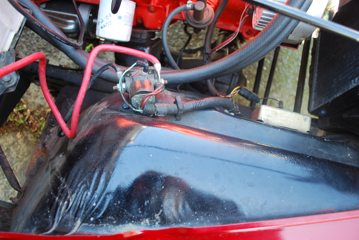
After making my diagram, consulting with Mr Stern, and ordering the parts I set to work by spending a bit of time beneath the hood figuring out the best location to mount the new relays, etc. Here's a shot of my chosen location before any modifications have been made.
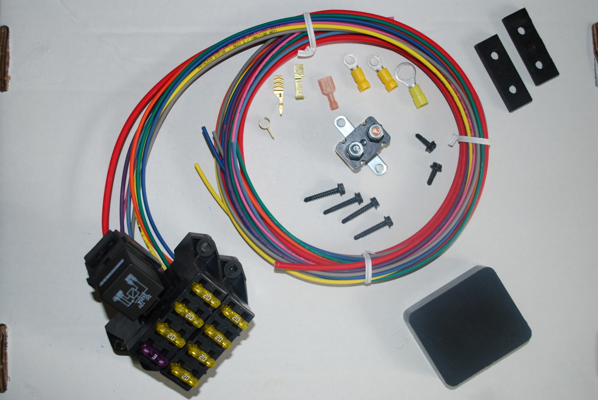
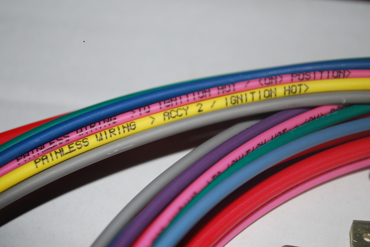
As the parts began to arrive I set to work. First order of business was the installation of the Painless auxiliary fuse block. The construction of it is quite nice - very solid and clearly water resistant (I don't know if they make a claim of water *proof* but it should certainly fend off spray coming in under the hood with no difficulties). The kit consists of the fuse block (with fuses), the attached relay, wires all connected and set in epoxy, a flexible cover to go over the fuse block, a circuit breaker to install in-line between the battery and the relay, and various connectors to hook up the wiring. The wires set into the fuse block and relay are about eight feet long - plenty to lay things out before cutting to length. The kit includes both spade and glass tube fuse adapters for attaching the ignition-hot lead from the Jeep's original fuse block (to control the relay for the ignition-hot fuses). One other thing to point out is the thoughtfulness of having each wire leading from the fuse block labeled. Great attention to detail.
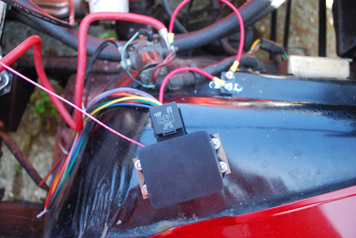
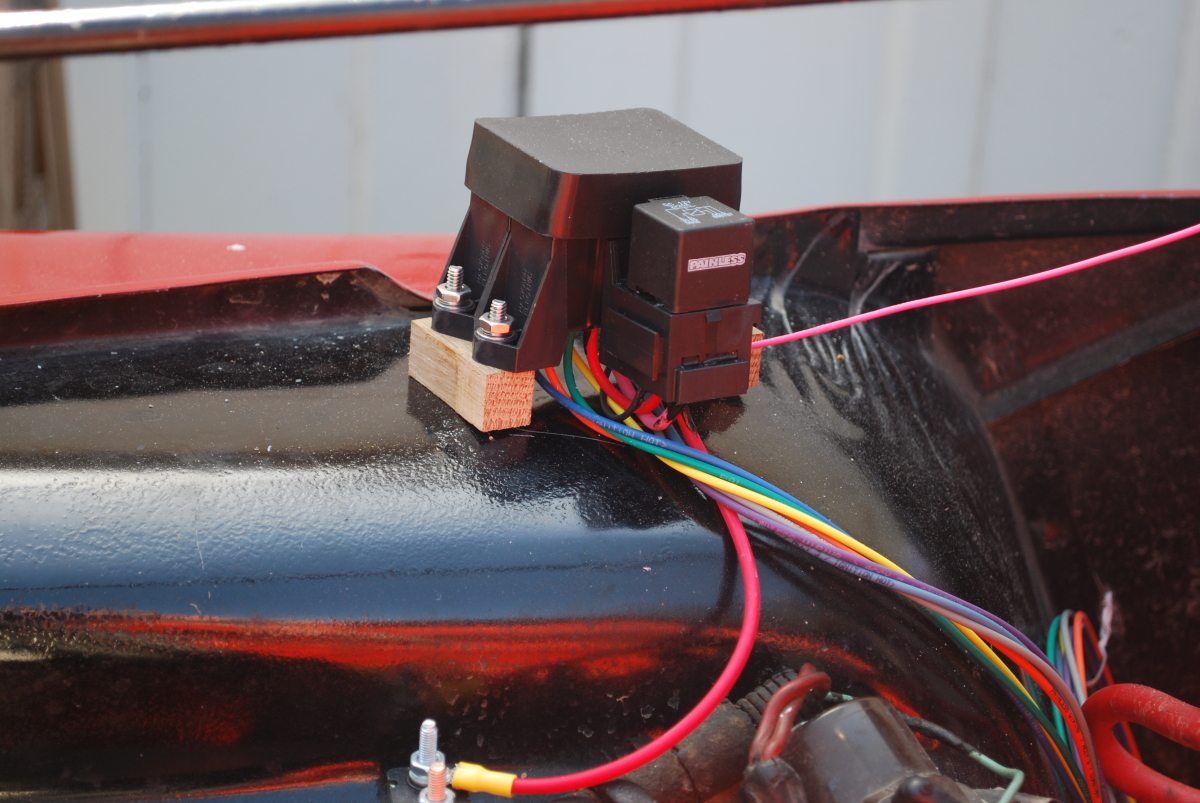
One of the things I found in attaching the fuse block and relay is that the wiring emerges from the bottom of the assembly (where it is set in epoxy) in such a way that it really requires about an inch of clearance if one doesn't wish to forcibly bend the wires nearly flat. There are enough wires that this would make a bit of a mess - and some of those wires are of a heavy enough gauge that I didn't want to risk tearing them loose from their epoxied connections. The kit comes with two spacer blocks to address this - but they are only about one quarter inch thick. So I worked around this by creating two blocks about an inch thick out of some white oak I had sitting around. It'll be weather resistant (I use this stuff in building boats) and is certainly strong. Some two inch stainless screws running through the wheel well, the oak blocks and then held down with some lock washers and nuts holds the entire assembly quite securely. You can see the result below on the bottom left.
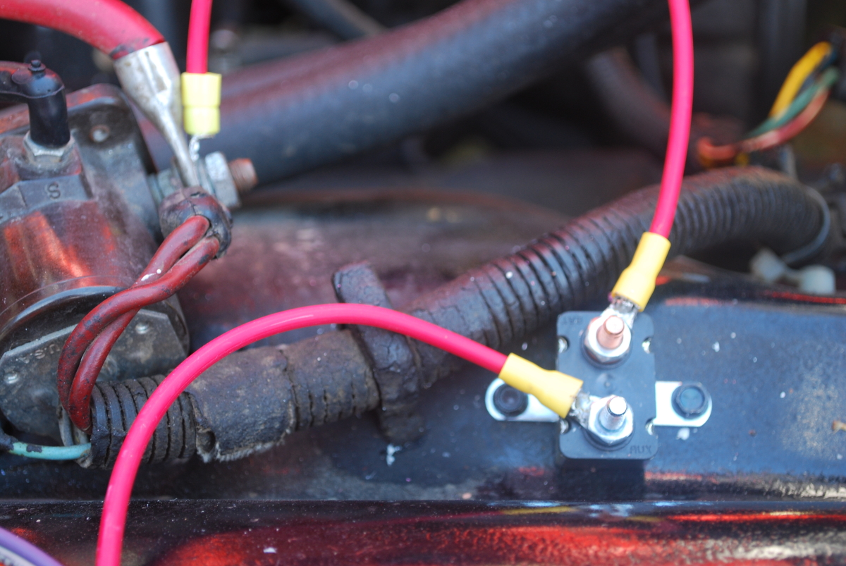
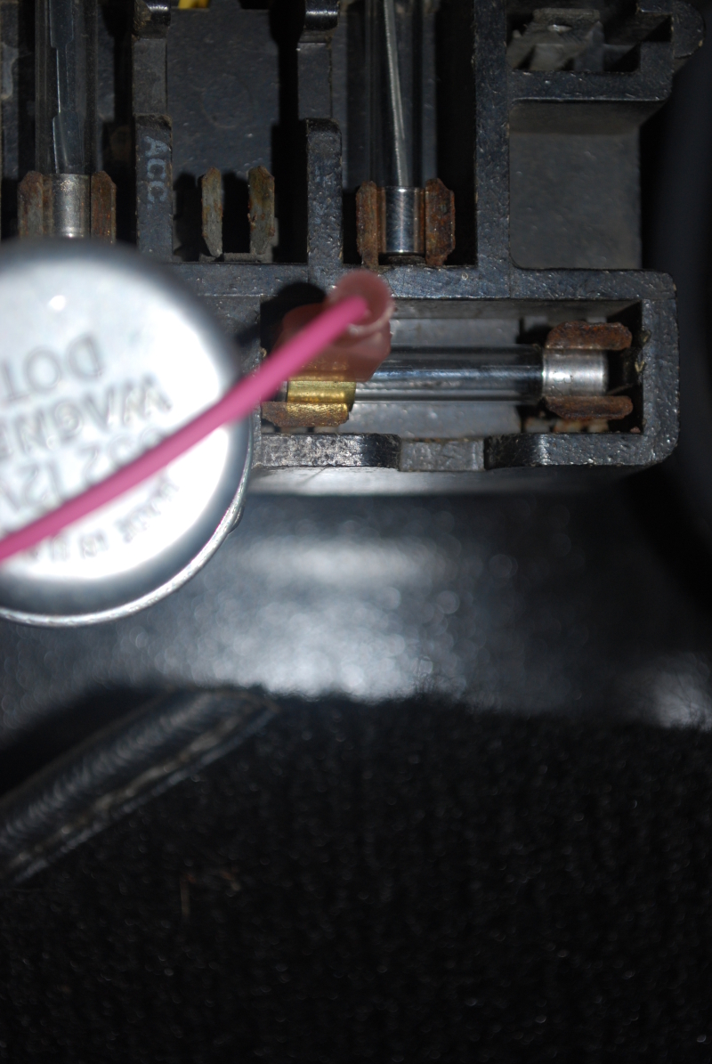
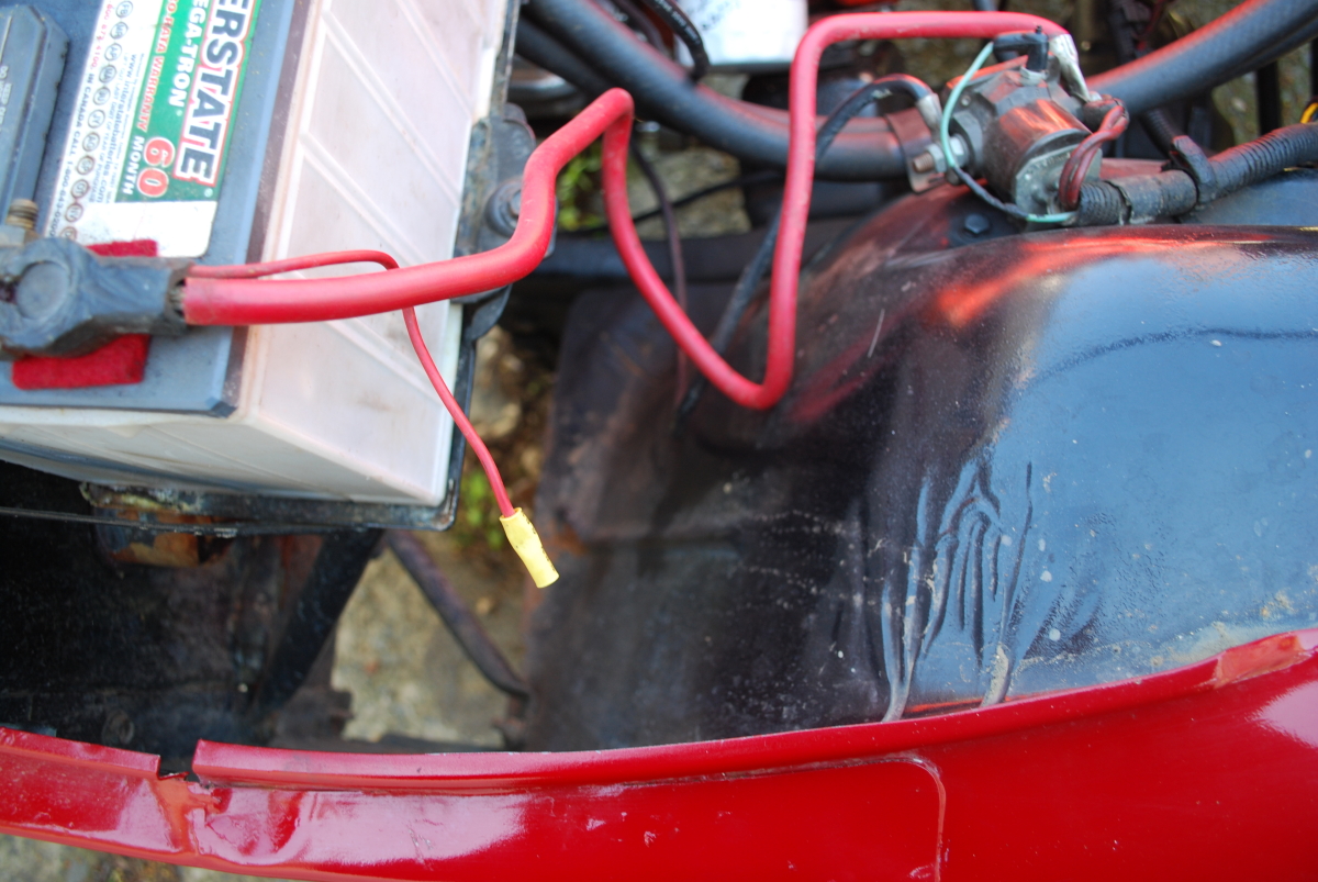
Finally, you'll see in the picture on the right the connection to the existing fuse block under the dash. A simple matter of popping out the SME fuse, wrapping the connector around the end attached to the hot terminal on the block, and then pushing the fuse back in. I hadn't realized what horrible shape my fuse block is in - look at all that rust! I guess that's gonna go on the long-term project list. Oh, and a quick caveat: in the pictures on the left, the lighter gauge pink wire is the one routing to the fuse block in the picture on the lower right. I found that the wire was a tad short to route cleanly - so I ended up attaching it to the stays supporting the grill assembly. This wasn't particularly elegant so later I spliced in an extra length of wire run it along the edge of the firewall nicely. I also wrapped in in some wire loom to protect it. Just something to be aware of if you opt to mount the auxiliary block where I did.
Next, installing the new lamps and relays.
Next, installing the new lamps and relays.