My 1976 Jeep CJ-5
Find me on JeepForum
Carter YF Carburetor Rebuild
After a few false starts (such as rebuilding my vapor recovery canister) in figuring out why "Bob" was no longer idling properly (if at all), it became clear that a rebuild of the Carter YF carburetor was in order. The most obvious possibility was a bit of dirt lodged in the idle jet within the carb. This belief was further reinforced as I read the Jeep Forum posts about the YF—particularly JeepHammer's excellent overview of the servicing of the YF carburetor which I ended up following closely with great success.
So, with a carburetor that was functioning well under acceleration or fast idle (choke still engaged), but not at all at curb idle, and having eliminated the possibility of vacuum leaks, I set to work.
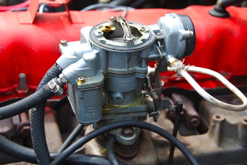
What I have under the hood is a Carter YF single barrel carburetor, model #7065S. This is not the original carb to this vehicle which would have been a 7109S as my CJ5 was not originally intended for sale in California. When I first bought the Jeep it wouldn't pass smog here in California, no matter how much the service guy fiddled with it. At that time I was very busy with work and could afford a remanufactured carb, and didn't have the patience to wait for the shop to rebuild it. So I had them drop this new unit in and all was well. Now that I've been laid off and have plenty of time—but no money to pay someone else to do the work—I opted to rebuild using Napa's rebuild kit CRB 25613. One may also order kits from The Carburetor Doctor, a very helpful site/business located in Alberta, Canada though they seem to be much more expensive for the same rebuild kit.
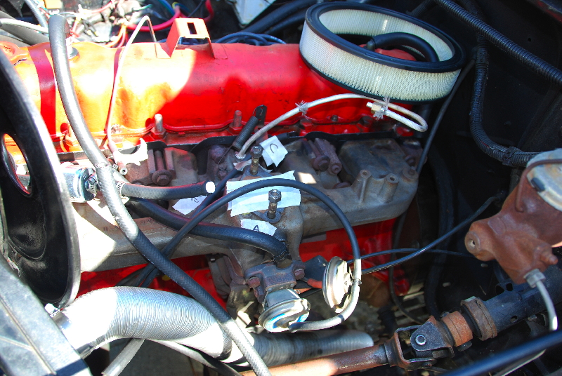
First order of business was to disconnect all of the vacuum hoses (there are four on mine—to the distributor, to the vapor recovery canister, to the air cleaner, and to the Coolant Temperature Override (CTO) switch), being sure to label them along with a corresponding label on the intake manifold adjacent to where each one connects. I also took a ton of photographs just in case.
Next task was to disconnect the connecting rod from the throttle lever to the throttle linkage on the throttle body (the lower third of the carb). Also, the pullback spring attached between the valve cover and the throttle linkage.
Finally, the choke heat tube from the exhaust manifold.
At this point the only thing keeping the carb in place are the two nuts holding it down to the studs from the intake manifold. These quickly came off and so did the carb! Off to the bench for disassembly it went.
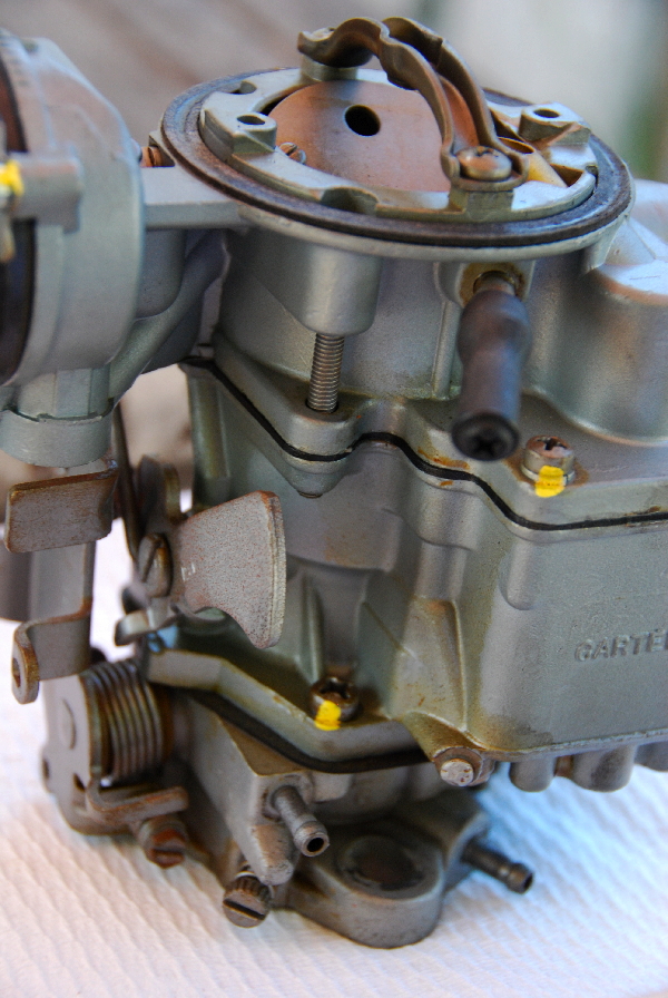
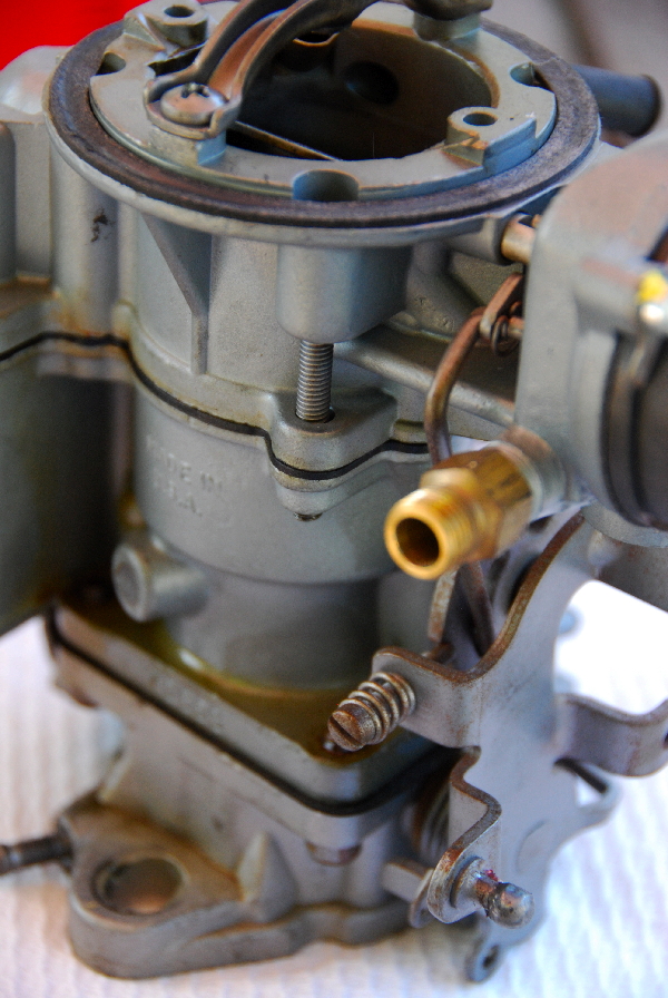
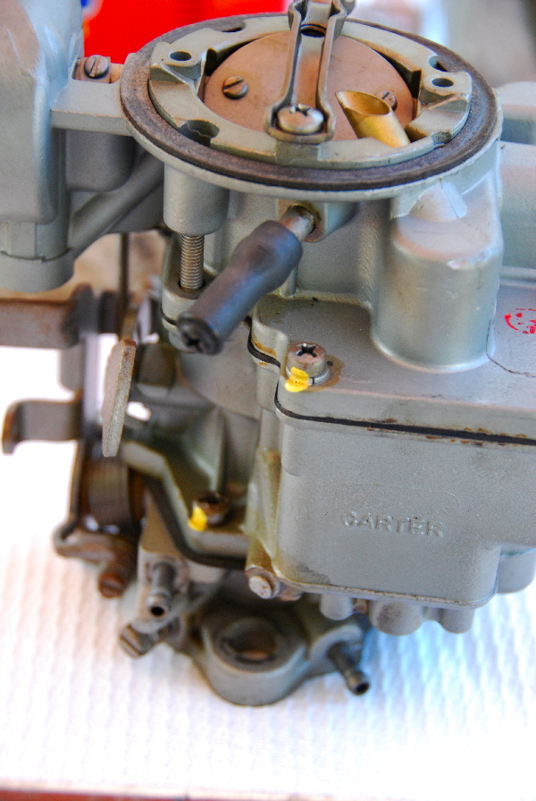
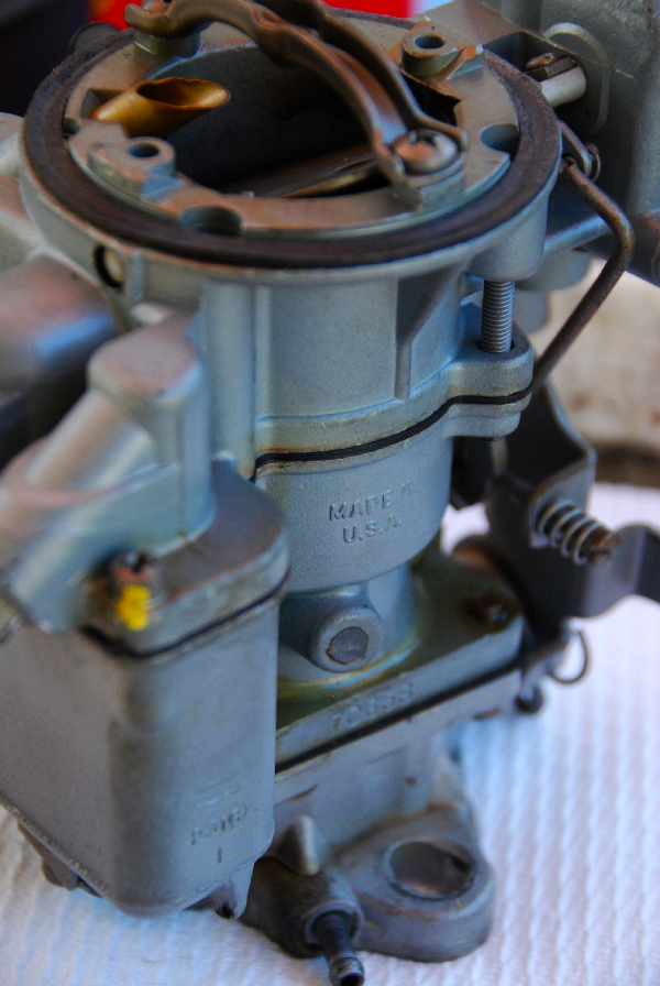
One thing of interest in the pictures above beyond the general overview of the carb from various angles: the capped-off vacuum port that, in some applications, is intended to supply clean air from the air-cleaner to the choke (routing through the choke heat tube). Mine doesn't have this provision and so that port is capped.
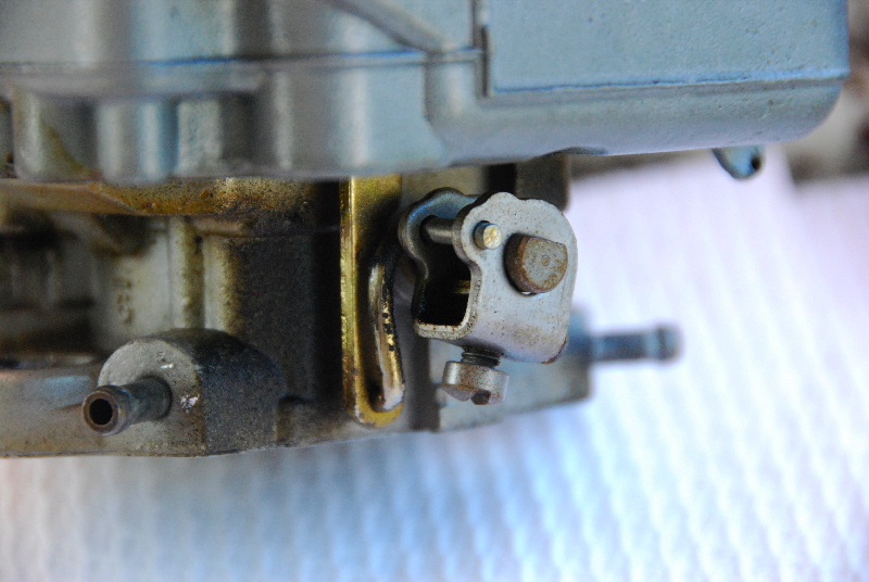
In the upper-left picture you see the pump arm (connected to the throttle linkage through the throttle body) and its link to the accelerator pump lifter link which extends down from within the main body of the carb.
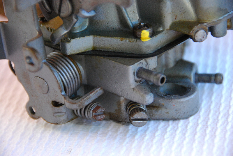
In the upper-right picture you see the idle mixture screw (right) and the curb idle adjustment screw (slightly smaller and to the left). In place these are both most easily accessed from the passenger side of the vehicle—reaching across the engine with a stubby screwdriver to turn them. A good rule of thumb for initial adjustment of these is: screwed in until LIGHTLY bottomed out and then back out four turns for the idle mixture screw, and screwed in and back out one and one half turns for the curb idle screw. This should at least get you fired up for fine tuning.
In the upper-right picture you see the idle mixture screw (right) and the curb idle adjustment screw (slightly smaller and to the left). In place these are both most easily accessed from the passenger side of the vehicle—reaching across the engine with a stubby screwdriver to turn them. A good rule of thumb for initial adjustment of these is: screwed in until LIGHTLY bottomed out and then back out four turns for the idle mixture screw, and screwed in and back out one and one half turns for the curb idle screw. This should at least get you fired up for fine tuning.

Above left is a view directly down into the main body of the carburetor. Of particular interest in this instance is the idle jet. It's the brass thing in the lower center of the picture with the hole in the middle and the slot cut across the top (for unscrewing). Immediately next to it (up and slightly left in this picture) is the economizer port. Further up and to the left, the other brass item, is the discharge weight sitting atop the (hidden) discharge check ball. These wear out over time and replacements are included in the rebuild kit.
Above right is a view of the upside-down airhorn with the float laying down across the fuel inlet needle and seat assembly. Another item of interest in this picture is the round diaphragm below the float. This is an aluminum disc which, when pressure within the float bowl exceeds a certain tolerance, lifts to allow the bowl to vent to the vapor recovery canister.
Above right is a view of the upside-down airhorn with the float laying down across the fuel inlet needle and seat assembly. Another item of interest in this picture is the round diaphragm below the float. This is an aluminum disc which, when pressure within the float bowl exceeds a certain tolerance, lifts to allow the bowl to vent to the vapor recovery canister.
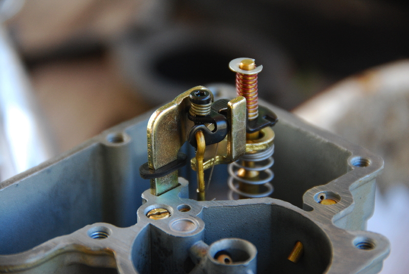
Here we have the top of the accelerator pump and metering rod assembly. The large flat gold colored piece is the pump lifter link which extends through a passage down and out the bottom of the main body of the carb to connect to the pump arm. As the pump arm is rotated by the throttle linkage it lifts the pump lifter which pulls on the pump diaphragm. Various parts of this assembly are also replaceable and come in the rebuild kit. In this particular instance I saw no need to touch anything. It's all just over a year old (since remanufacture) and everything is in good working order.
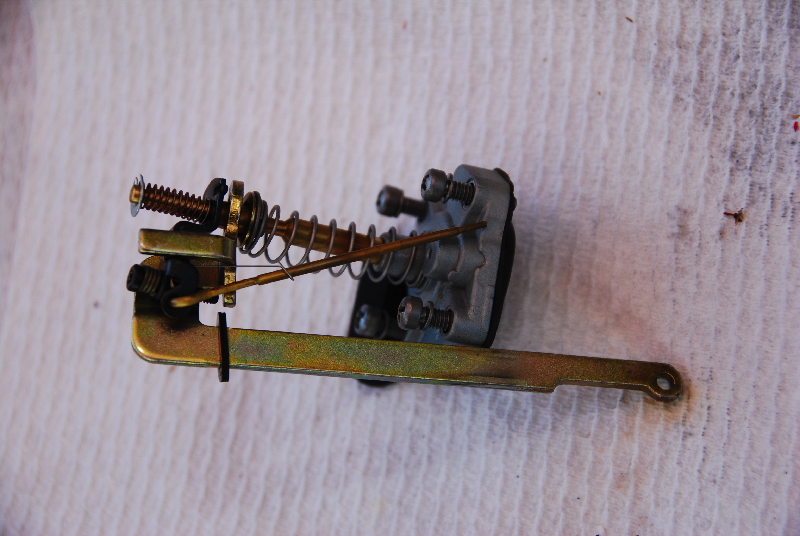
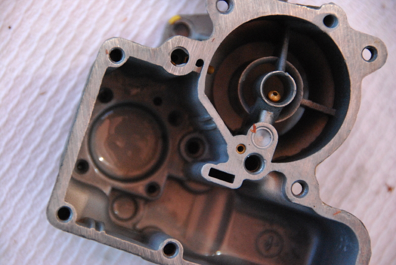
Below, left, is the pump assembly removed but intact. Below, right, is a view of the float bowl with the pump assembly removed. Disregard the bits of orange you see, leaves from one of our trees were falling while I was doing this work. I was careful to ensure none of 'em made their way into the reassembled carb!
Below, left, is the pump assembly removed but intact. Below, right, is a view of the float bowl with the pump assembly removed. Disregard the bits of orange you see, leaves from one of our trees were falling while I was doing this work. I was careful to ensure none of 'em made their way into the reassembled carb!
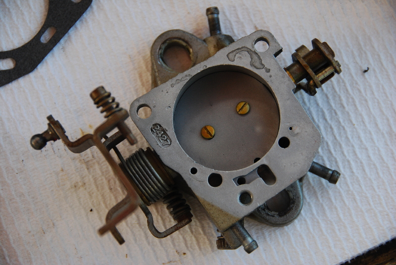
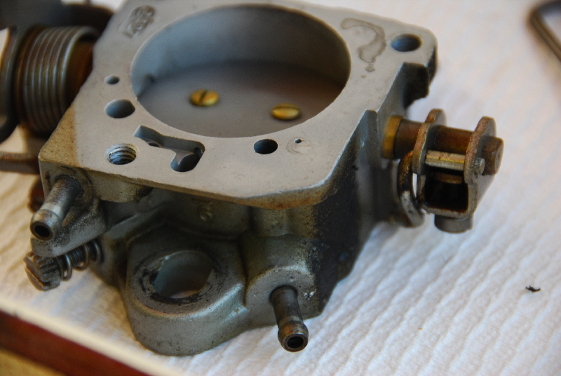
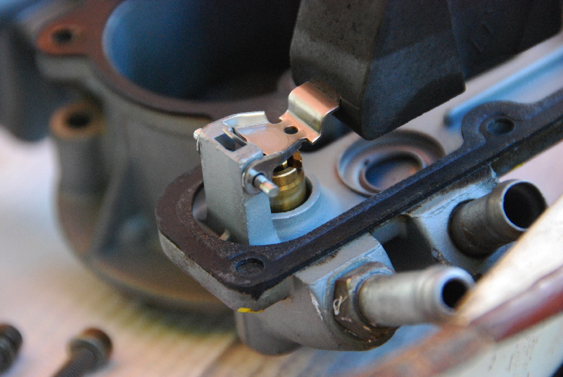
The last bit of our tour is just an overhead view or two of the throttle body itself. In the upper left-hand picture one can see the throttle linkage, with the curb idle and fast idle adjustment screws, the nob which connects to the rod running down to the throttle lever and, on the right side a view of the pump arm from above. Note also the various vacuum ports leading to the outlets for the distributor vacuum advance (right hand) and the CTO switch (left hand).
In the picture to the right above is just a better view of the pump arm and the pump connector link. Be aware that this link is not retained in any way when the main body of the carb is separated from the throttle body. Don't lose it!
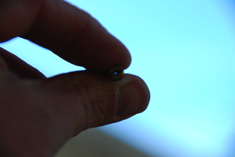
And now we come to the suspected cause of the idle problem: the idle jet. Remember that slotted brass screw mentioned above? When unscrewed from the main body it is about two inches long. Holding it up to the light I could clearly see an obstruction inside (near the lower end opposite the threaded end). I asked my wife for a thin sewing needle, slid it through and out popped a little bit of crud. You can see it next to the jet in the picture below right. That pesky little bit of dirt was completely screwing up the engine's ability to idle.
In the picture to the right above is just a better view of the pump arm and the pump connector link. Be aware that this link is not retained in any way when the main body of the carb is separated from the throttle body. Don't lose it!
And now we come to the suspected cause of the idle problem: the idle jet. Remember that slotted brass screw mentioned above? When unscrewed from the main body it is about two inches long. Holding it up to the light I could clearly see an obstruction inside (near the lower end opposite the threaded end). I asked my wife for a thin sewing needle, slid it through and out popped a little bit of crud. You can see it next to the jet in the picture below right. That pesky little bit of dirt was completely screwing up the engine's ability to idle.

Having cleared the idle jet and re-inserted it into the main body, I did a bit of double-checking to ensure things like the float were set to spec (using the handy little paper ruler that came with the rebuild kit) and then I re-assembled everything with new gaskets. I didn't use the new bits of hardware for the check-ball, accelerator pump assembly, etc., figuring the ones I had were only a year old, looked perfectly good, and the parts I now have on hand may come in handy for a quick repair some day.
Once everything was back together—having spent a minute or two ensuring that the pump connector link between the pump arm and the accelerator pump lifter link was properly connected I went back to the Jeep to prepare the intake manifold. When I pulled the carb off earlier in the day I took care to cover the opening in the manifold to prevent anything from falling down in there and getting sucked into my cylinders. I taped over the opening with masking tape. Were this to be a project of longer duration I'd probably find something a bit more substantial like a large rubber stopper.
I cleaned the last bits of the old gasket from the manifold—taking care not to drop any of the debris down the manifold opening—sanded smooth the phenolic resin spacer to ensure a good, tight fit between manifold and carb and then re-seated the carb. It doesn't take too much to bolt it back down, 12 to 15 foot pounds of torque. I reconnected the vacuum lines, the choke heat tube, the throttle connecting rod, and the pullback spring to the throttle linkage and all was set.
I was quite please that "Bob" fired right up and, after warming up and coming down from fast idle, was back to idling as smooth as can be expected of the 258. I even brought the curb idle down a bit and leaned out the idle mix. My tach only goes down to about 900 rpms so I need to get a more accurate one to see if I'm down to the 500-600 that's specified in the FSM.
A quick test drive around town to ensure all is well and "Bob" is back in business!
A quick test drive around town to ensure all is well and "Bob" is back in business!