My 1976 Jeep CJ-5
Find me on JeepForum
Carter ABD Carburetor Rebuild
Okay, this has absolutely nothing to do with my (or any other) Jeep. But given the lack of information out on the internet regarding this particular, excellent, carburetor I figured I'd better document the rebuild.
Background: A friend of mine owns a 1962 Lincoln Continental. It's black with a black interior and—best of all—it's a drophead/convertible. Totally awesome. One of the cooler cars to ever come off an assembly line. Slab sides, suicide doors. In the words of Carl Spackler, "striking..."
Due to more pressing concerns, my friend parked the car in 2008 at the onset of the recession. I finally talked him into getting it running again six years later. So, we uncovered it one day in September and began the revival process. The whole process doesn't matter for our purposes here—there are numerous how-to's for firing up an engine that's been sitting for years (my favorite being the collected videos from Jeff Bradshaw's Red Neck Restorations)—but the Carter ABD interested me since it is rarely documented (on the internet anyway).
So here's the rebuild. Hope it's of interest and use for others.
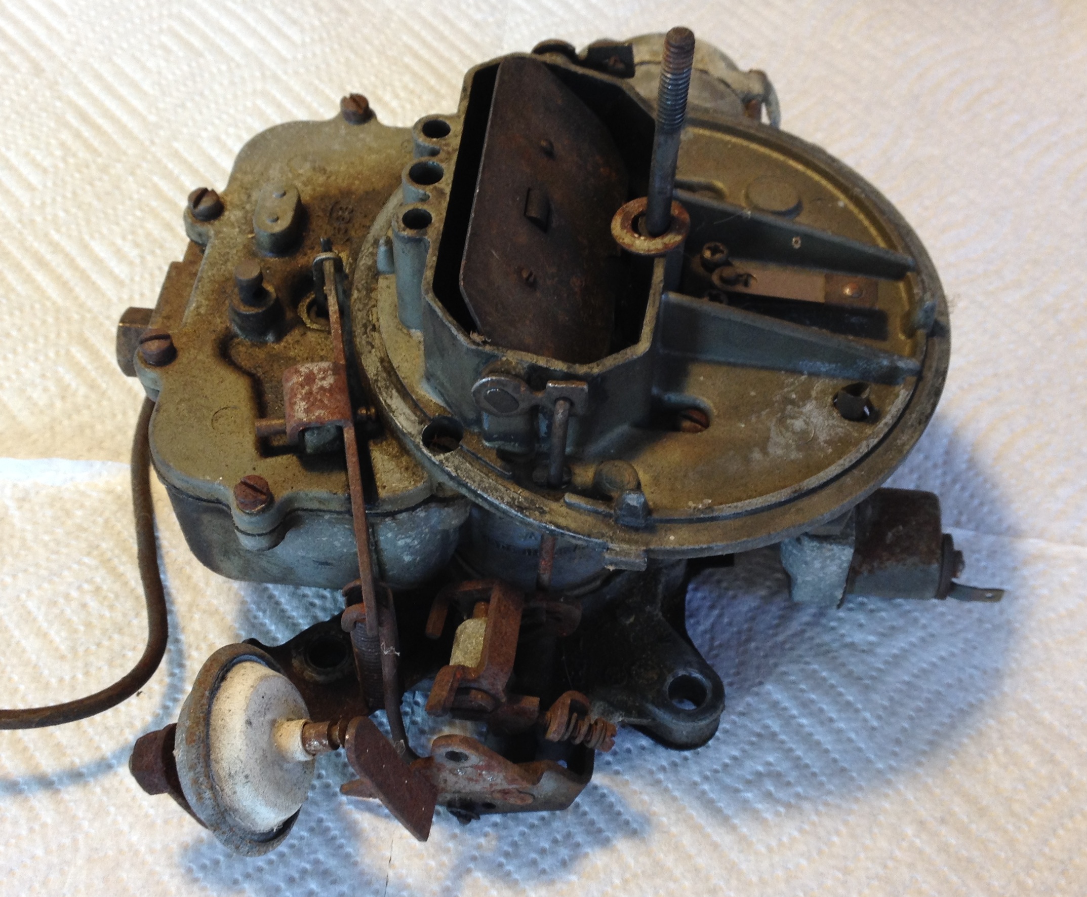
What we have here is a Carter ABD two barrel carburetor. From what I've read this was a good carb, introduced in 1959 and used primarily on Edsels, Lincolns, Mercurys and Fords in the US, but only until the early/mid 60's. However, Ford continued to use it on cars destined for export to Mexico, Central and South America throughout the 1960's. It hasn't left a big historic footprint out on the interwebs. In tearing this one down I have to say that it's really very nicely designed and built. There's a symmetry to it that is visually pleasing. As with many things, if it looks right it probably is right.
Unfortunately for us, this particular unit had a few issues. The choke piston was frozen, the accelerator pump barely moved and the anti-stall dashpot was adjusted such that it was completely inoperative (I'd find out why shortly). A rebuild was definitely required.
Unfortunately for us, this particular unit had a few issues. The choke piston was frozen, the accelerator pump barely moved and the anti-stall dashpot was adjusted such that it was completely inoperative (I'd find out why shortly). A rebuild was definitely required.


First order of business was acquiring a rebuild kit from Mike's Carburetors. It's not a cheap kit (I'm used to $20 for my Jeep's Carter YF) but, given the rarity of the unit I don't suppose that's surprising. We paid about $75 plus shipping.
As with many rebuild kits, the part numbers in the exploded diagram provide a fairly good indication of the order in which one dismantles the unit (and later rebuilds it in reverse order). I find it helpful to think of the components of a carburetor such as this one as a group of discreet sub-assemblies. As I remove them I find it helpful to set them aside together—in this instance putting them in ziplock bags.
First order of business after removing the various linkage arms was removal of the hot idle compensator. This is essentially a plug that opens by means of a temperature-sensitive metal strip. When under-hood temperatures get high enough that fuel begins to vaporize in the float bowl—which will cause idling issues—the metal strip bends, thus opening the vent to allow additional air to be pulled in directly to the intake manifold. This raises engine speed which has the effect of cooling things overall.


The next step was removal of the air horn (the top third of the carb). To do this one must first disconnect the accelerator pump arm from the anti-stall dashpot and then remove it from the top of the air horn. Then, assuming all of the linkages are disconnected*, the air horn can be lifted free of the carb body.
*Having a carburetor pin tool makes disconnecting and re-connecting the linkages much easier. The little retaining clips are often referred to as "Jesus" clips because that's what you yell when you can't get hold of them with your big fingers and when you *do* get hold of them you drop them every time and lose them. Lisle makes the tool in question. Do yourself a favor, get one.
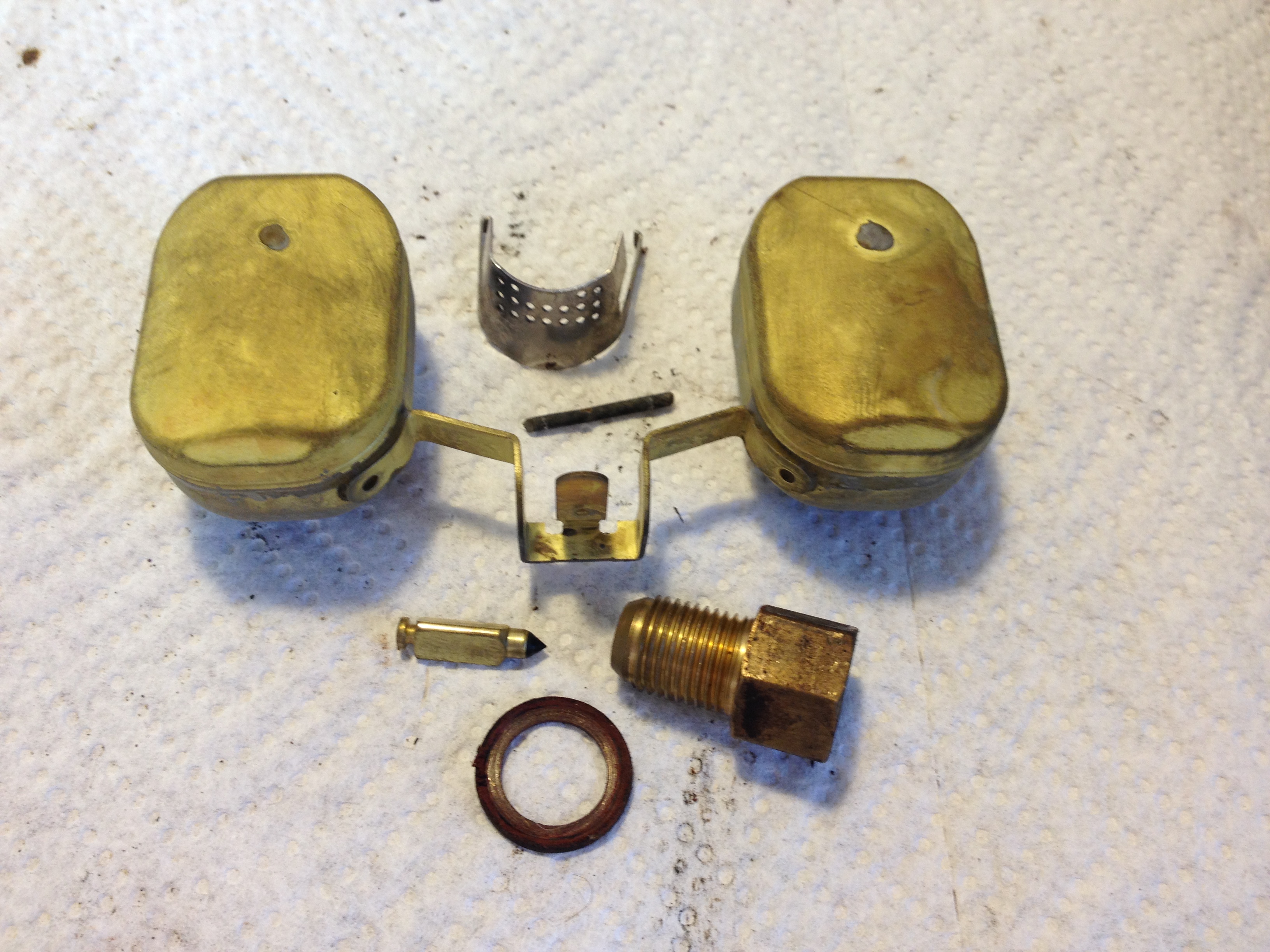
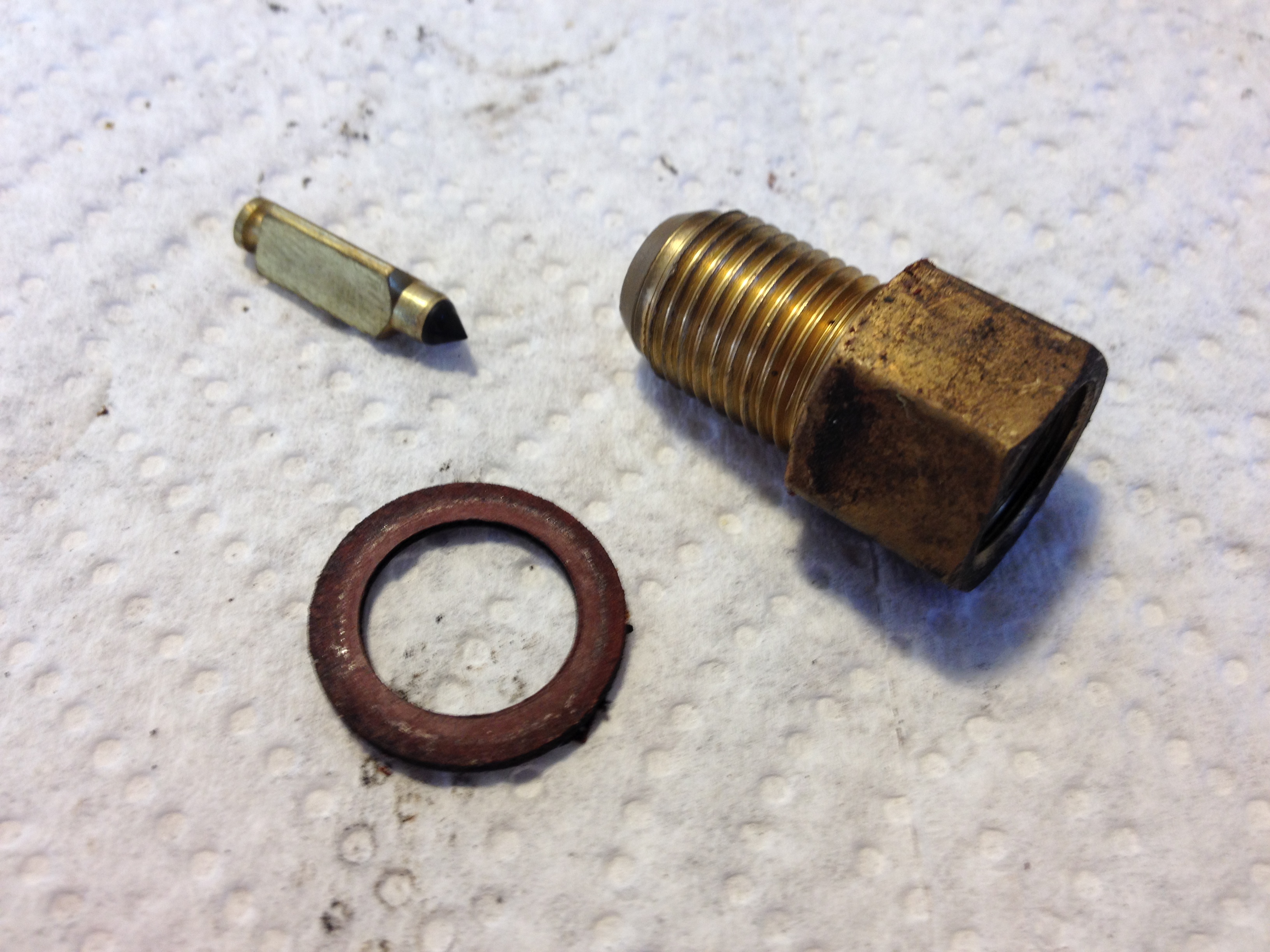
Once the air horn is removed the nice symmetry of the ABD design becomes apparent. What one is greeted with after removing the old gasket beneath the air horn is the float bowl with two brass floats, the accelerator pump, the vacuum piston and metering rods, and the booster venturi. Fuel flows into the bowl by way of a brass fitting into which the inlet needle seats. Here is the fuel inlet/float sub-assembly:
*Having a carburetor pin tool makes disconnecting and re-connecting the linkages much easier. The little retaining clips are often referred to as "Jesus" clips because that's what you yell when you can't get hold of them with your big fingers and when you *do* get hold of them you drop them every time and lose them. Lisle makes the tool in question. Do yourself a favor, get one.
Once the air horn is removed the nice symmetry of the ABD design becomes apparent. What one is greeted with after removing the old gasket beneath the air horn is the float bowl with two brass floats, the accelerator pump, the vacuum piston and metering rods, and the booster venturi. Fuel flows into the bowl by way of a brass fitting into which the inlet needle seats. Here is the fuel inlet/float sub-assembly:
Here is more detail on the vacuum metering system and the accelerator pump. The metering rods are quite delicate, don't want to bend those! As engine speed increases, manifold vacuum goes away and the spring beneath the vacuum meter forces it up. This draws the metering rods out of the main jet seats allowing more fuel to flow through.

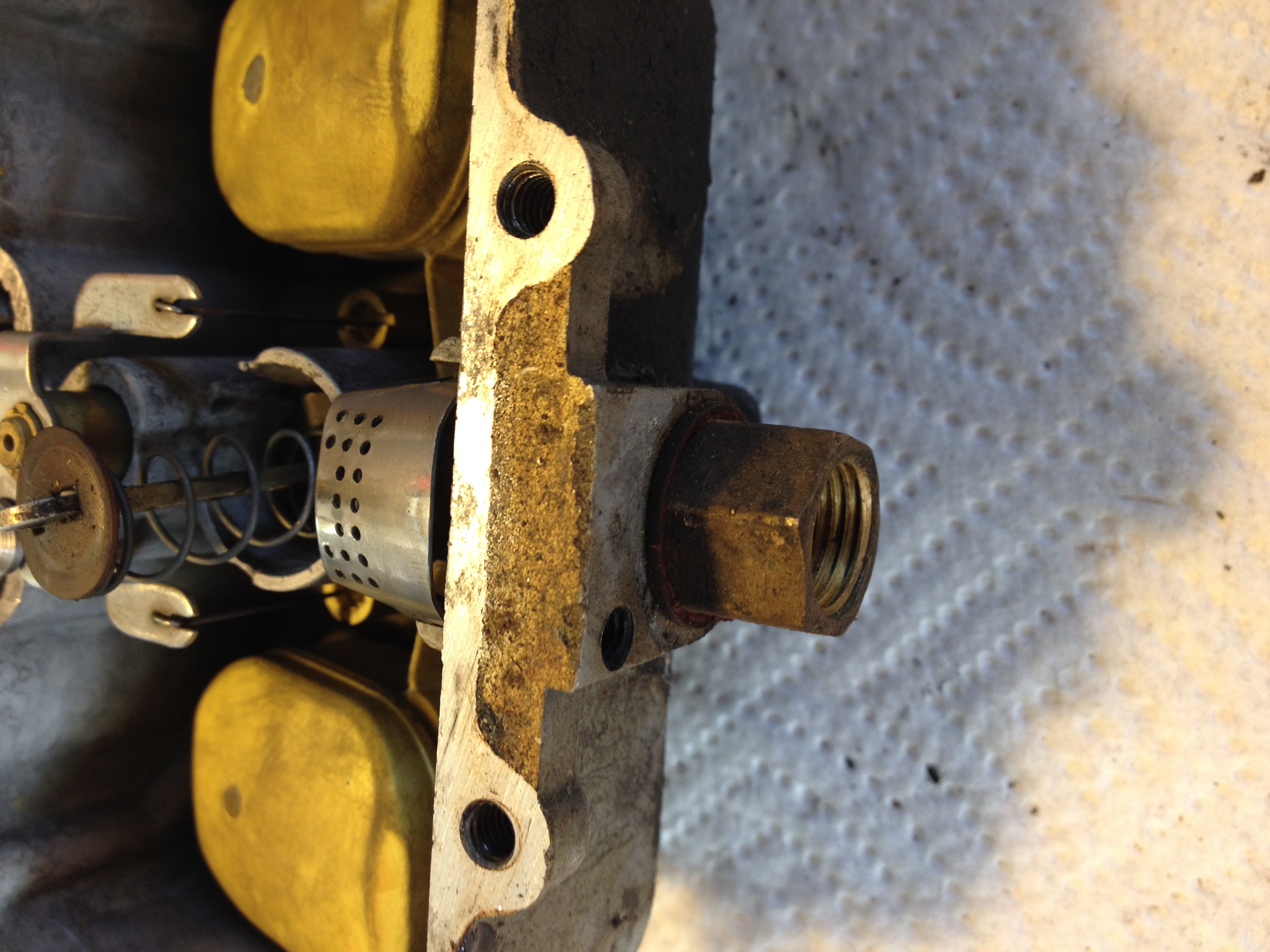
Having removed the vacuum metering components it's time to pull the vacuum pump. This assembly simply lifts out of its well. Beneath it is the pump inlet check-ball that allows fuel to be drawn up into the well as the pump valve is raised by its spring. The valve is depressed under acceleration by the arm attached to the throttle lever. This forces a shot of fuel into the pump jet. The rebuild kit includes a replacement ball bearing as well as a replacement for the leather gasket (the very worn pink thing in this picture).
After removing the accelerator pump the last thing in the float bowl are the two main jets. In this case these were in very nice shape given their age. I suppose it is possible the passages have been worn to a larger size over the past 50 years but I don't have a way to check that…
Below is a shot of the completely empty float bowl. Note the bit of cruddy residue coating the bottom of the bowl. Clearly this thing has been rebuilt at least once—no 50 year old carb is that clean.

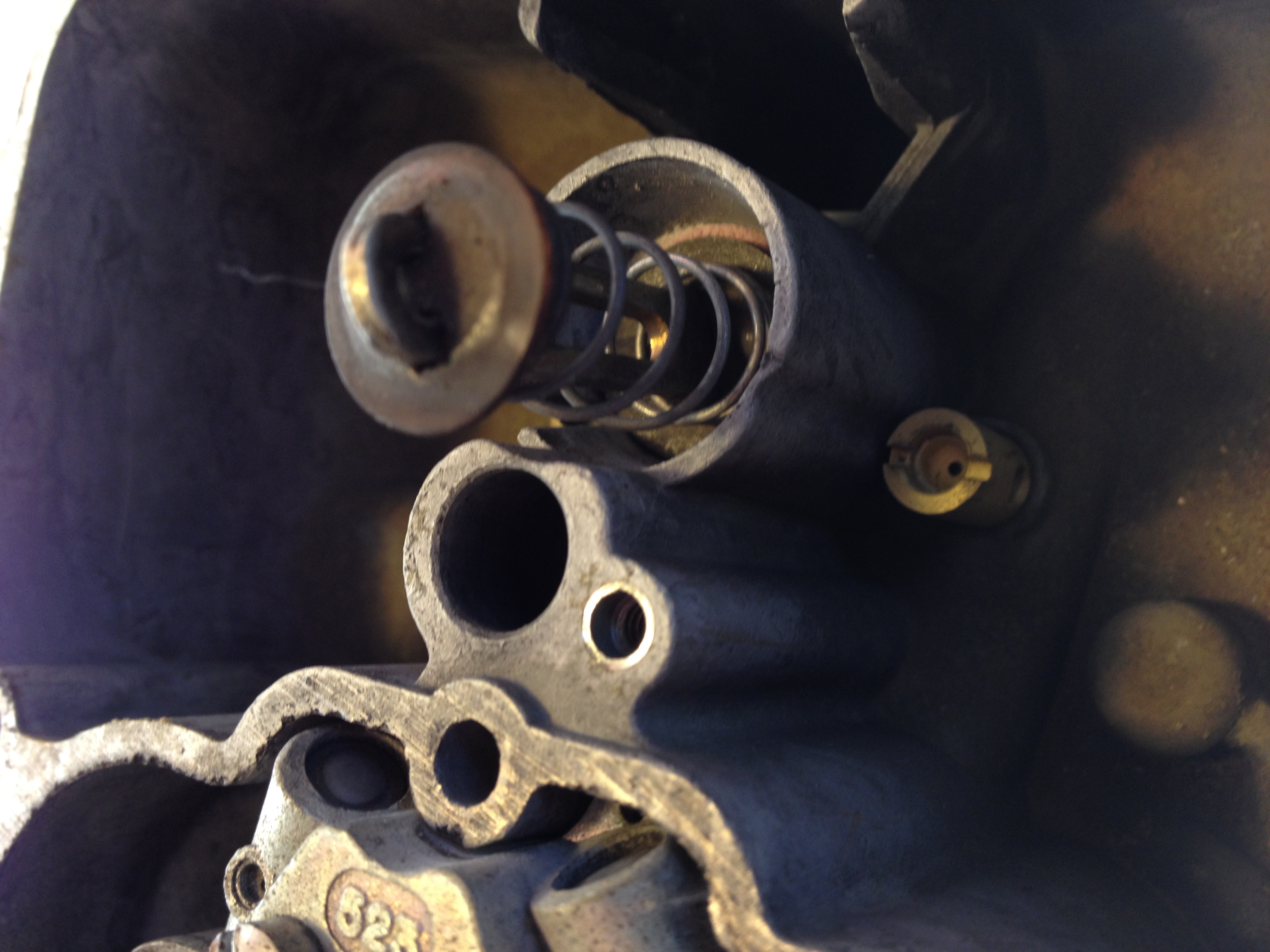
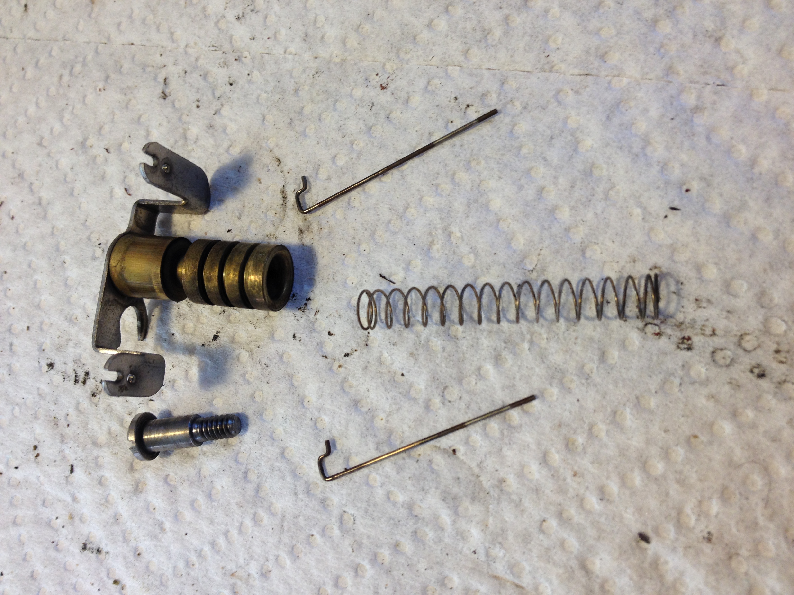
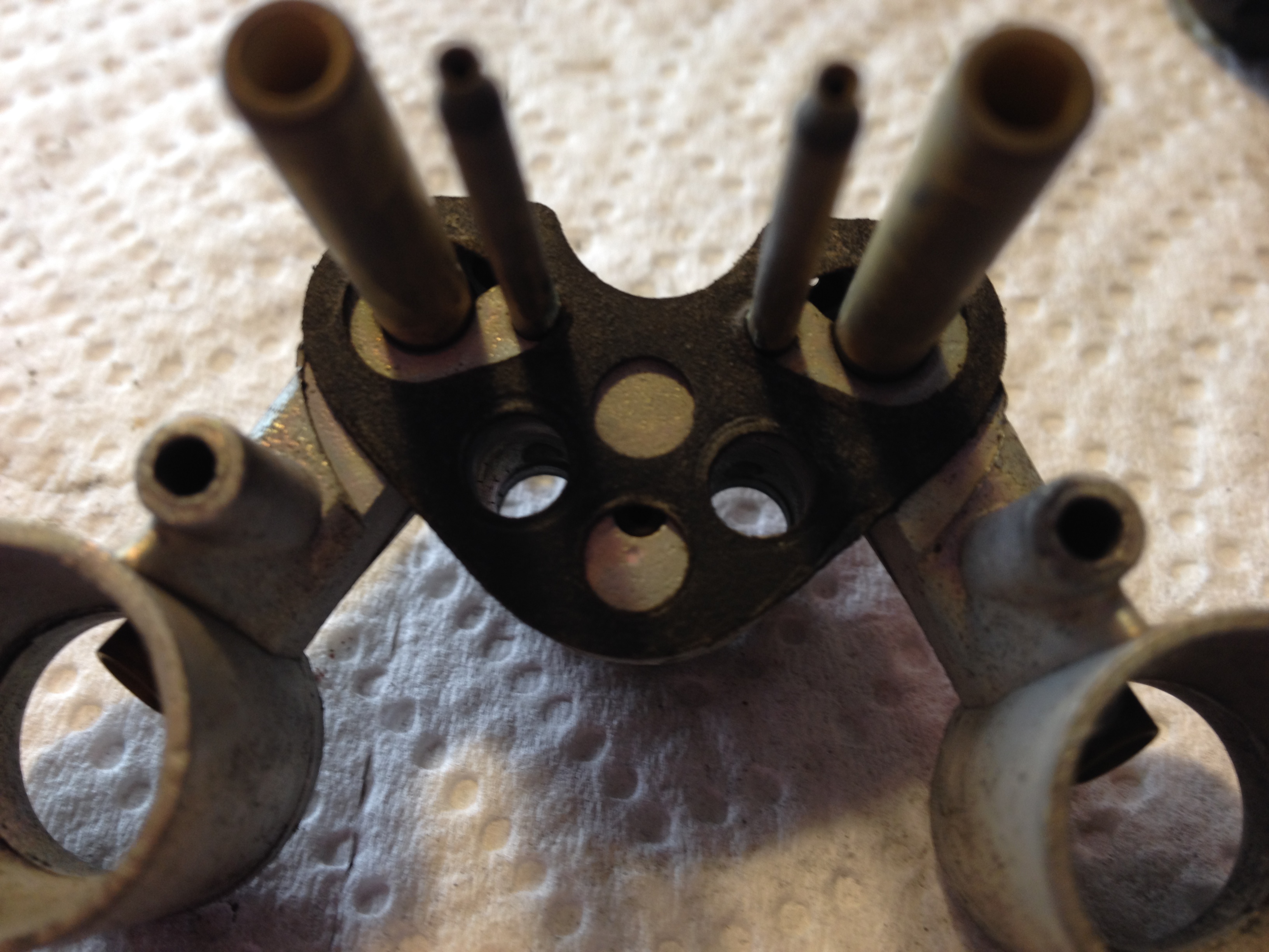
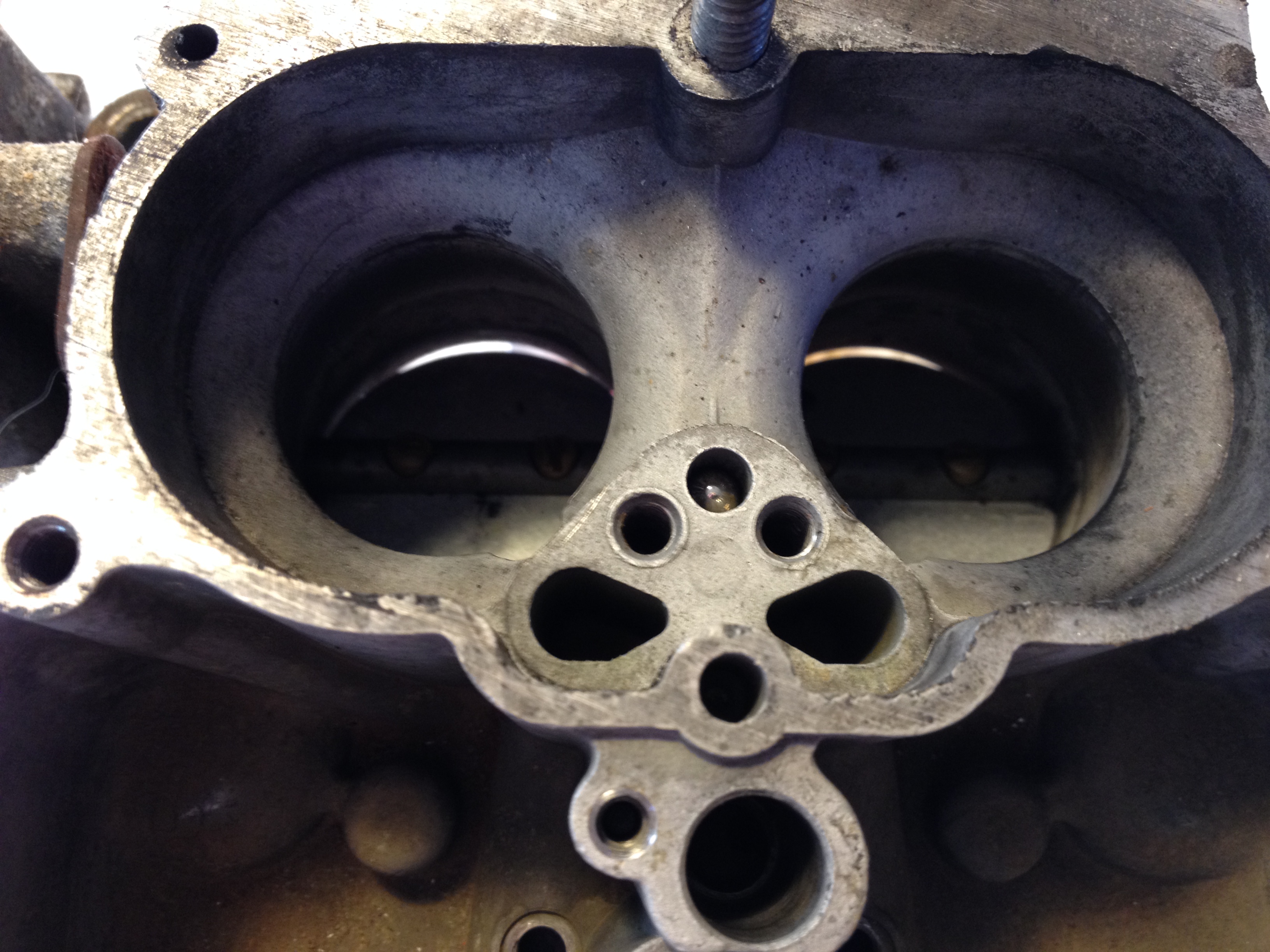
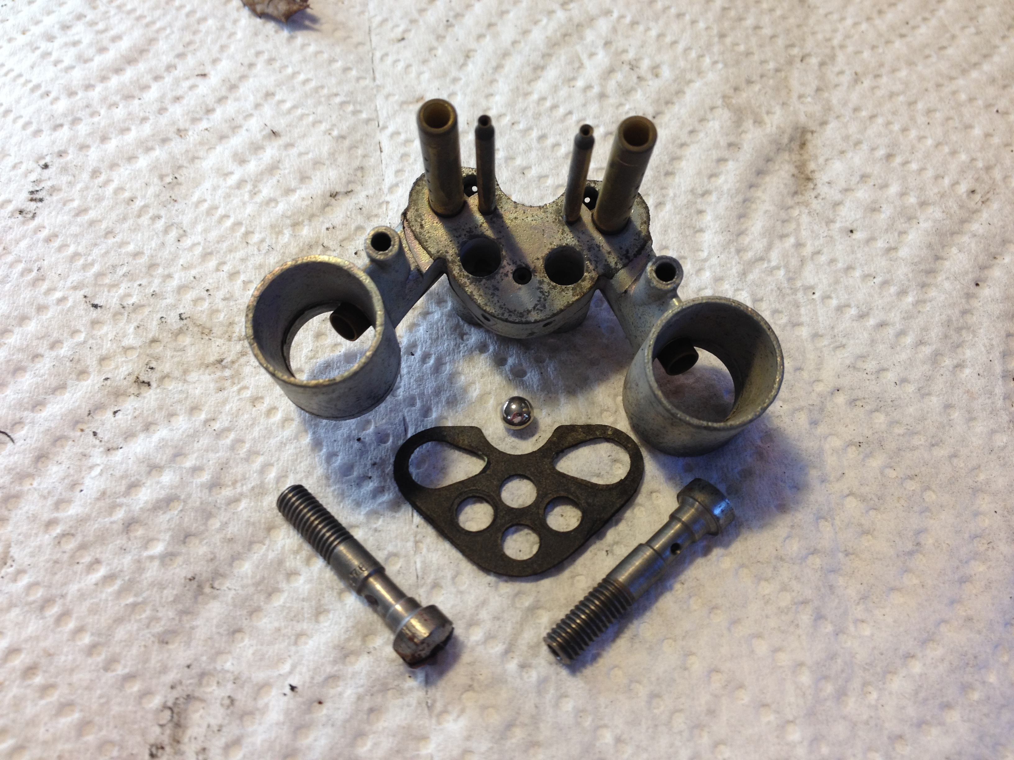
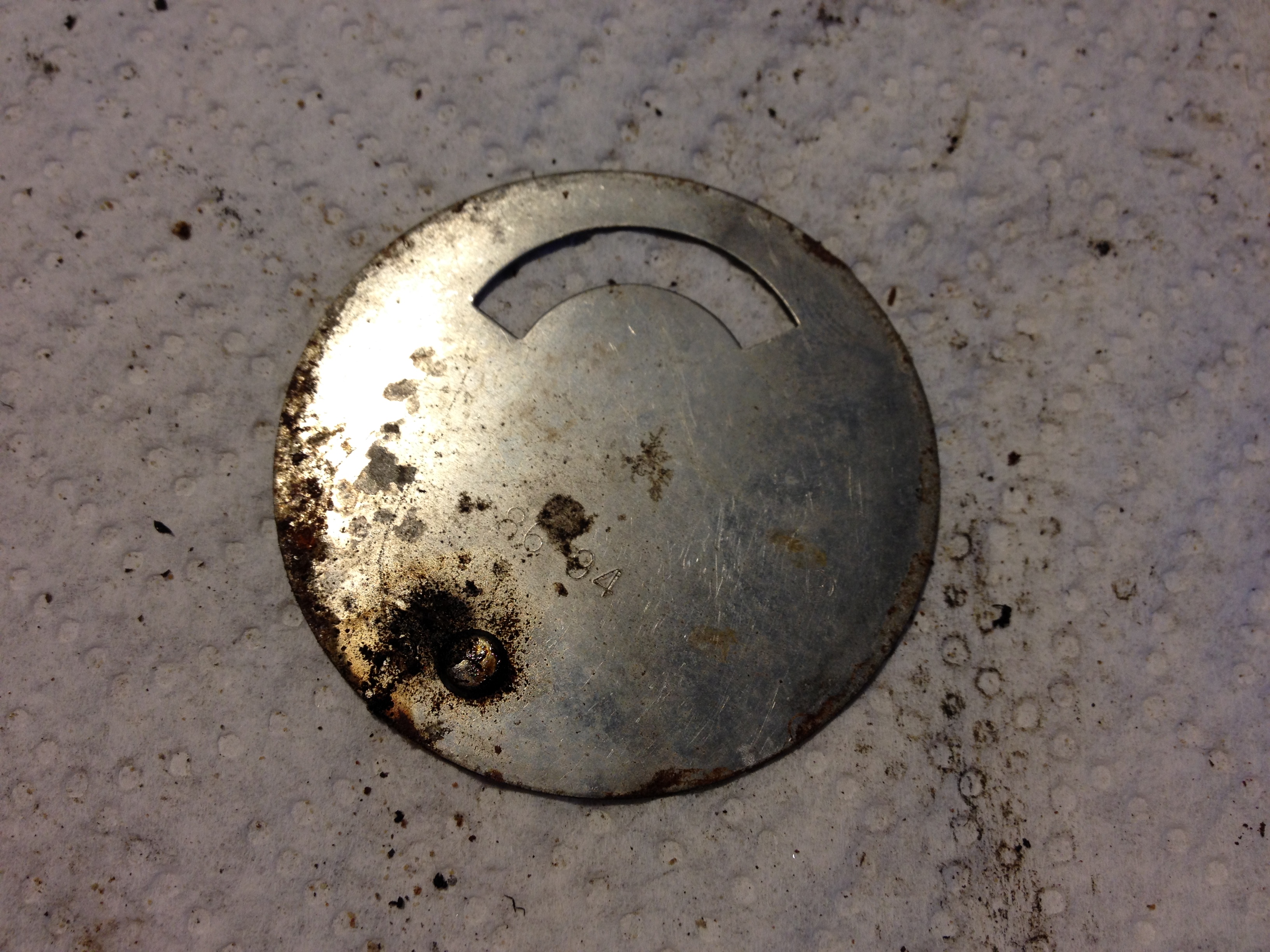
Next step is removal of the booster venturi assembly. This includes the booster venturi casting, the venturi cover, two pump discharge screws, and the pump discharge check-ball. Below are shots of the various pieces, the gasket, and a shot of the float bowl with the check-ball still in place so the hole it sits in is clear.
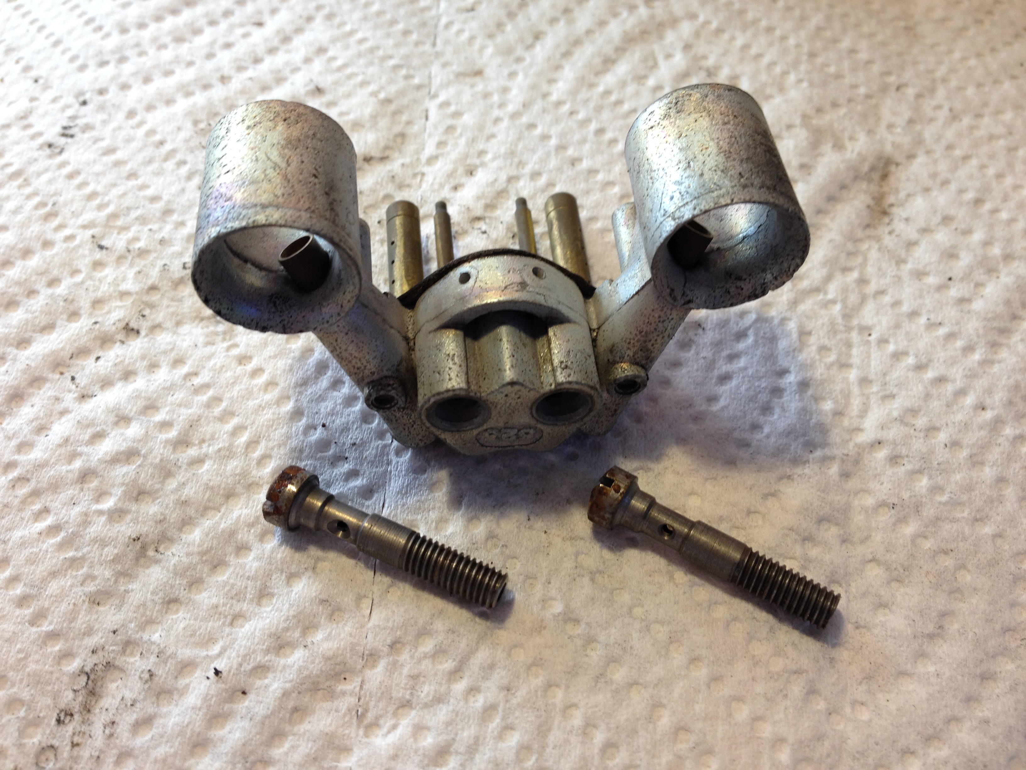
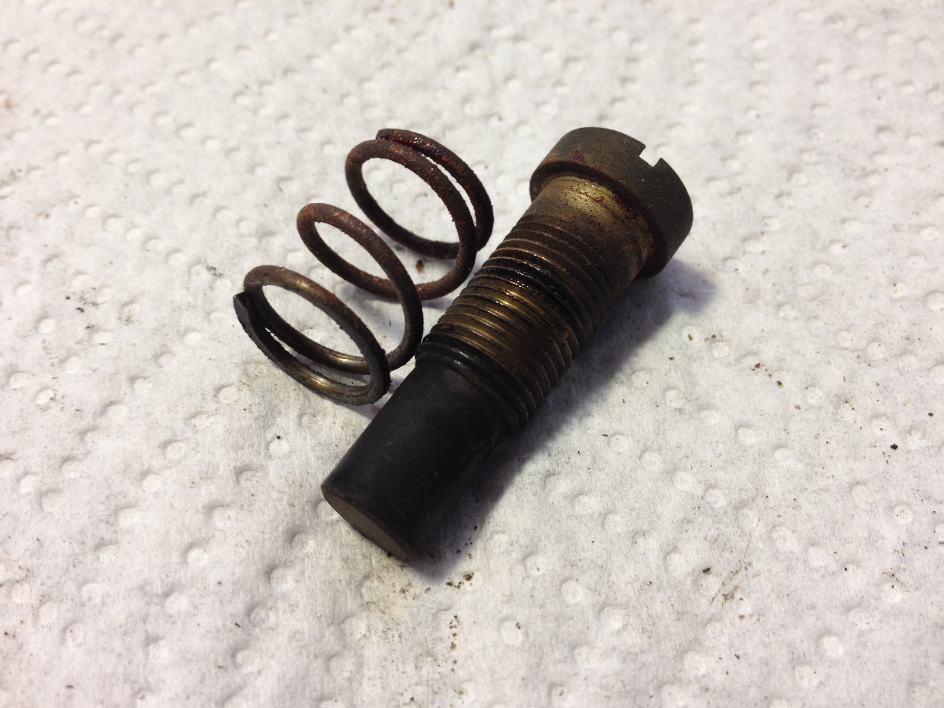
On the side of the float bowl opposite the fuel inlet is the idle speed adjusting screw. This controls the flow of air necessary to operate at idle as the throttle plates are closed at idle speed.
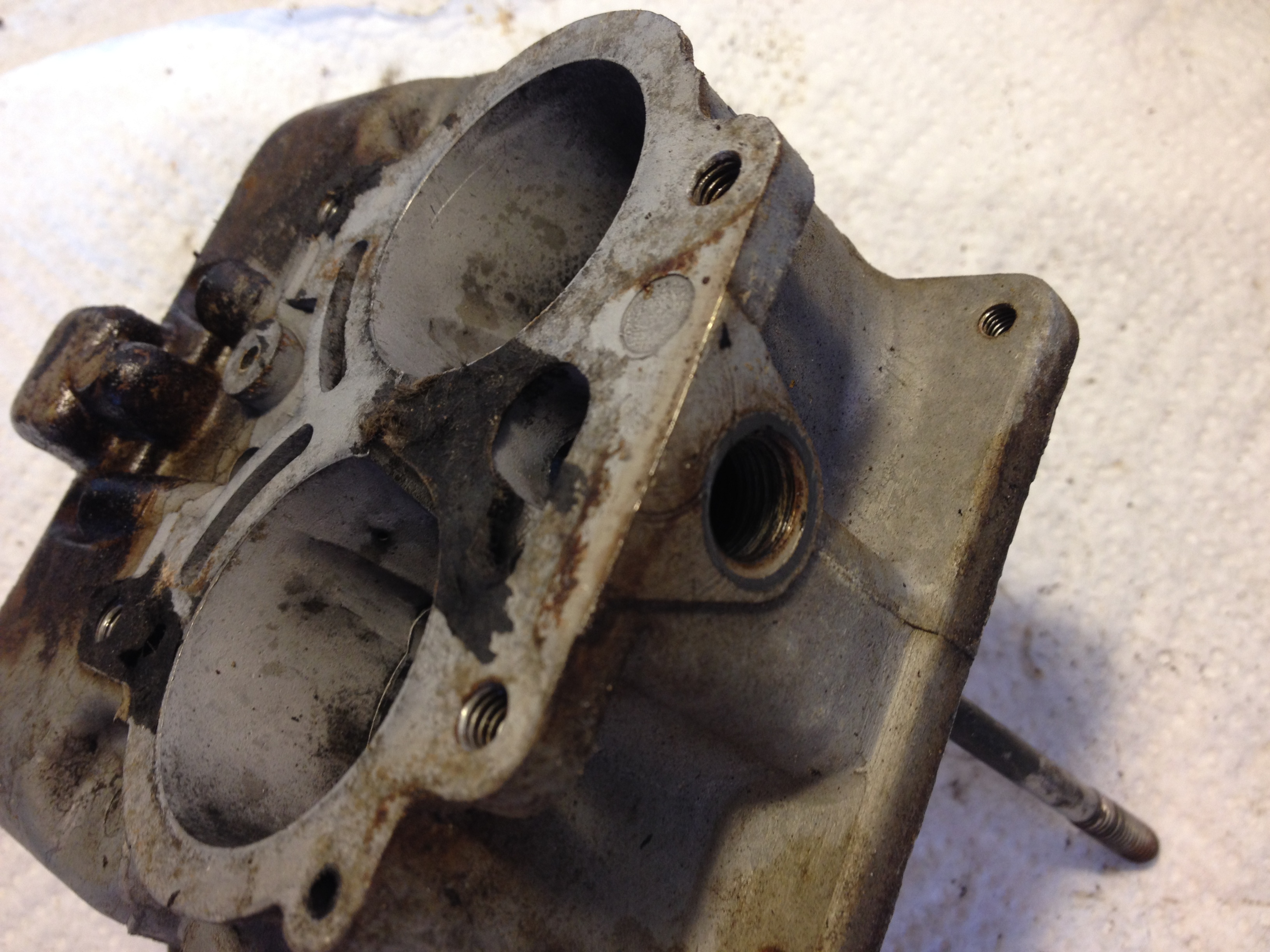
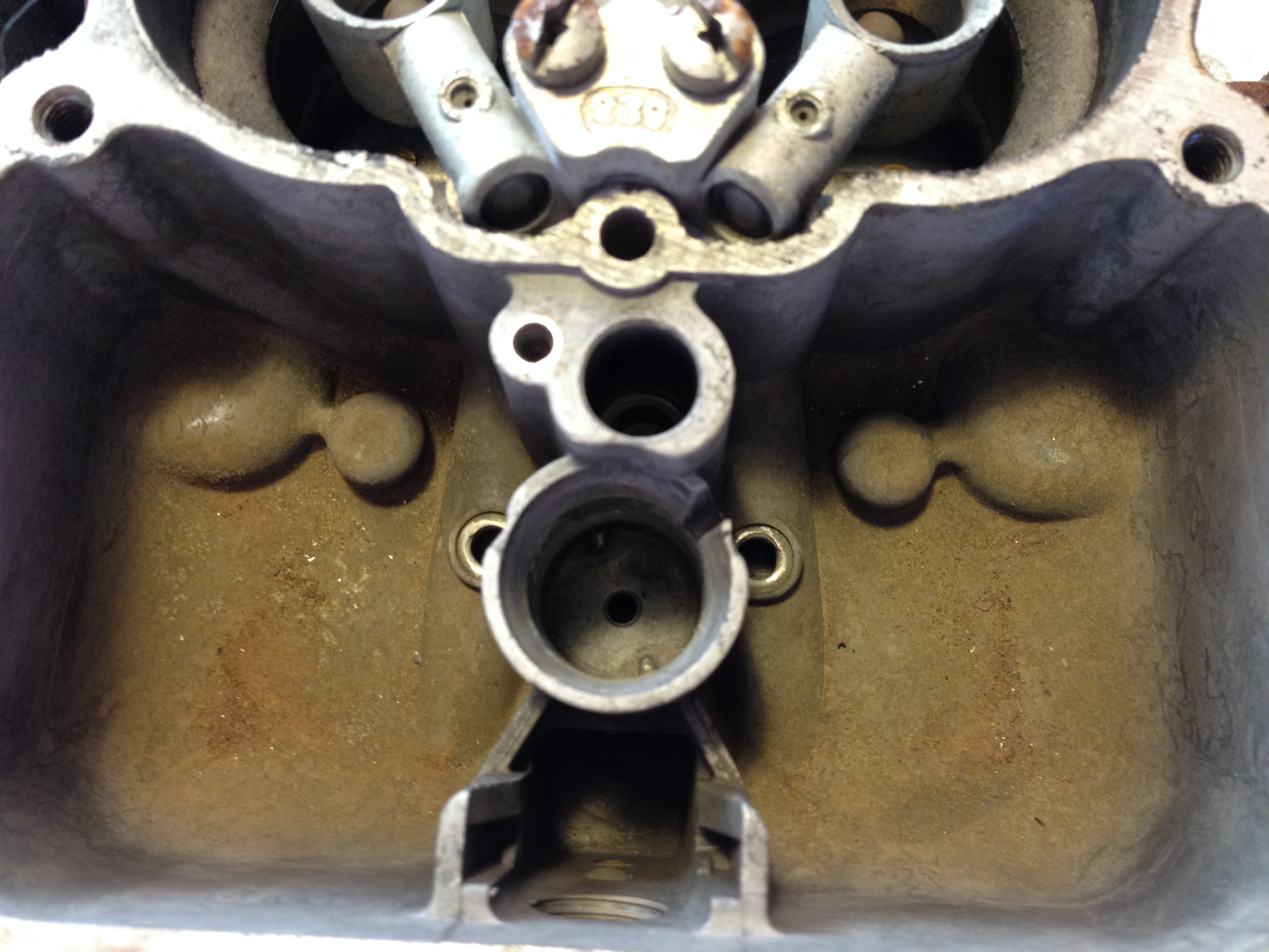
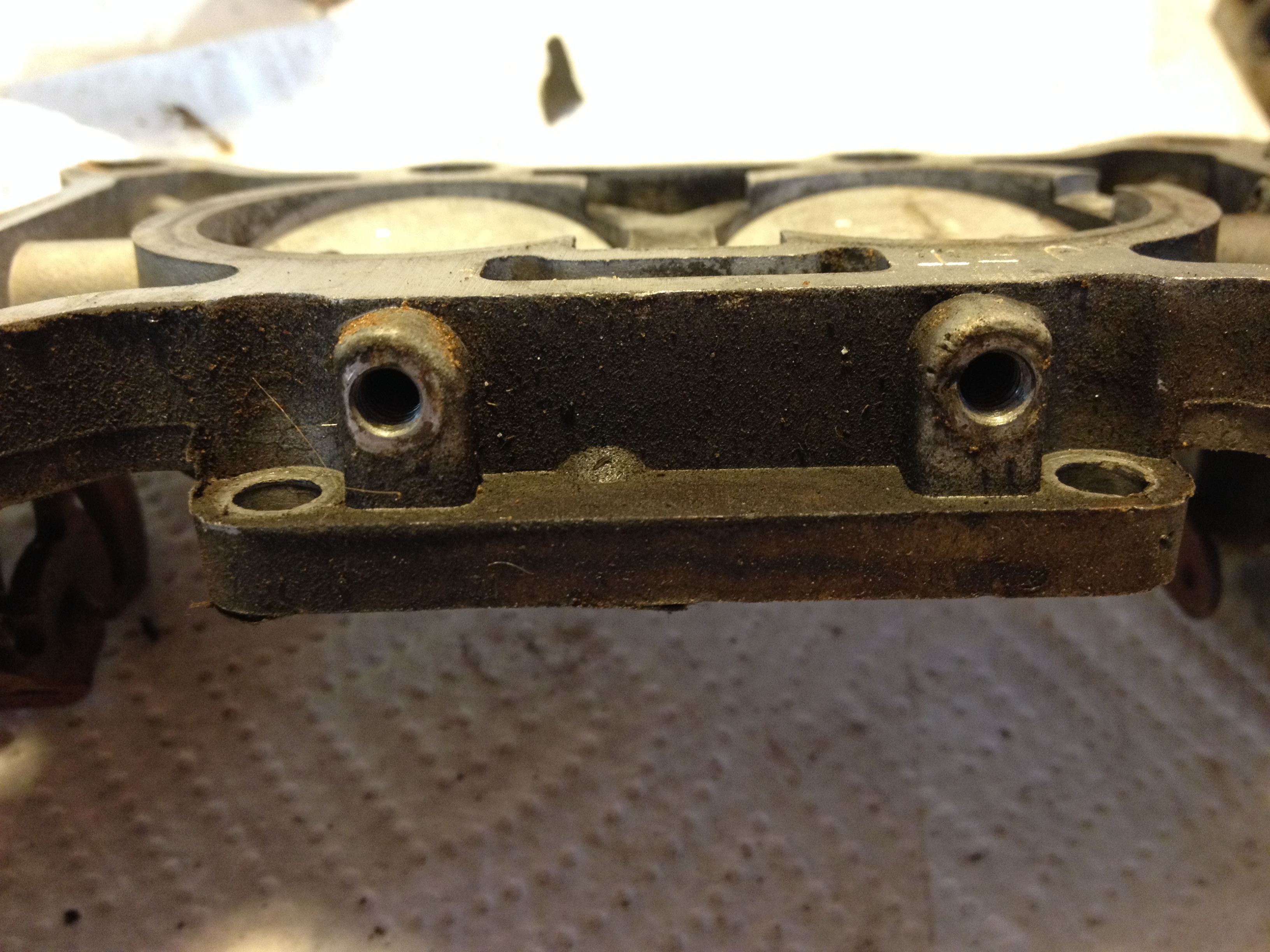
Next order of business is separating the now empty float bowl from the throttle body. The throttle body is still completely assembled (minus the linkages removed during the previous steps). Here are the two pieces separated (but before I removed the idle speed adjusting screw discussed above). There are four screws holding the two pieces together.

The throttle body has three areas of focus. First is the idle speed-up control (lower left and right pictures). This is a mechanism designed to compensate for the increased load on the engine when the air conditioning system (a York on the Linc—just the *best* compressor you can have if you are a Jeep owner) kicks in. When the York's electric clutch is engaged the resulting drag on the engine slow things down. So an electric signal is sent at the same time to the idle speed-up control solenoid which opens a valve allowing air to be drawn directly from within the air filter chamber—bypassing the carb—and into the intake manifold. Note that this is a sub-assembly that must be cleaned in pieces. There is a plastic tube that runs through the carb body that cannot be immersed in any sort of carb cleaner—same with the electric solenoid. So, be mindful here…

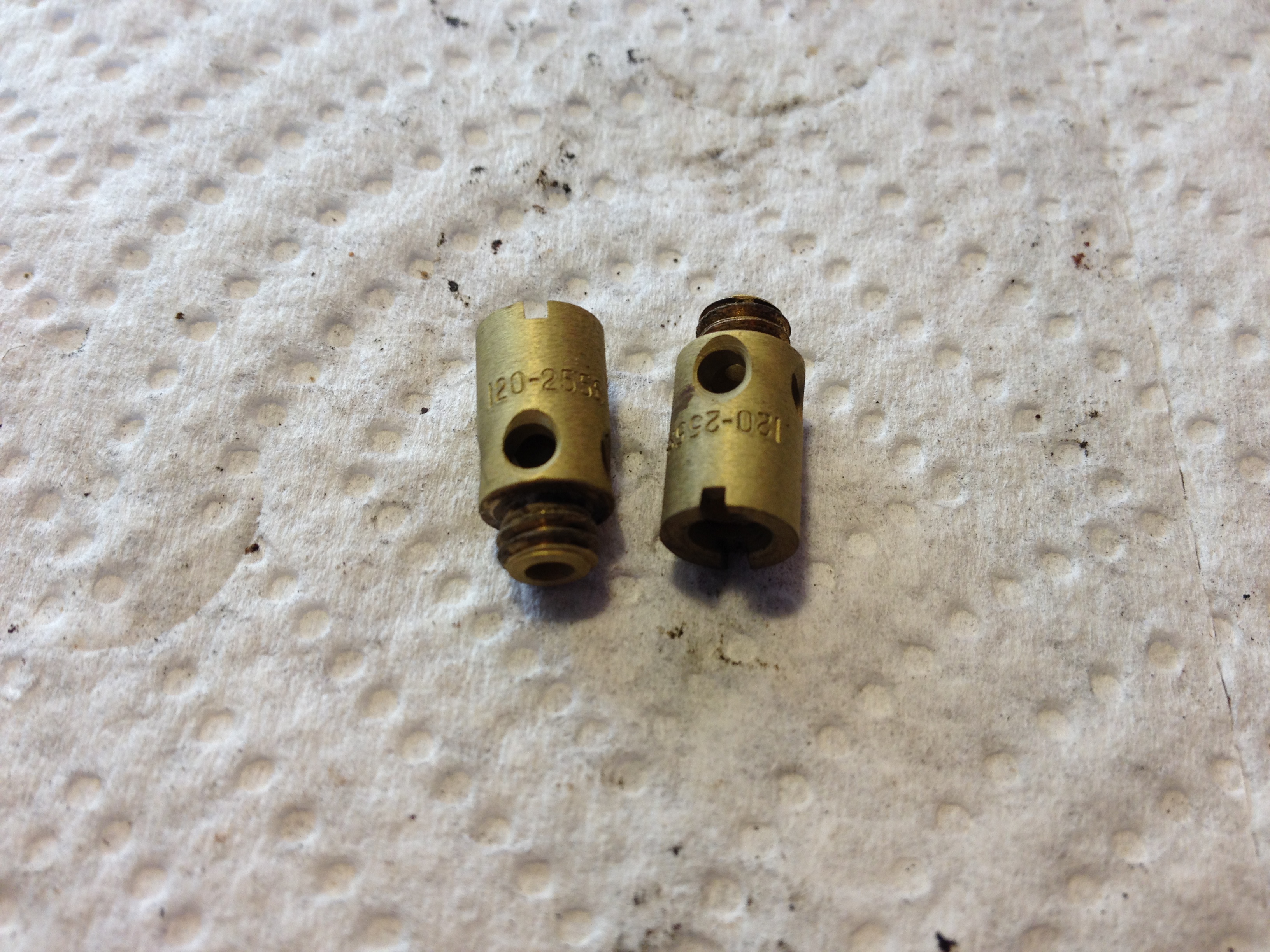
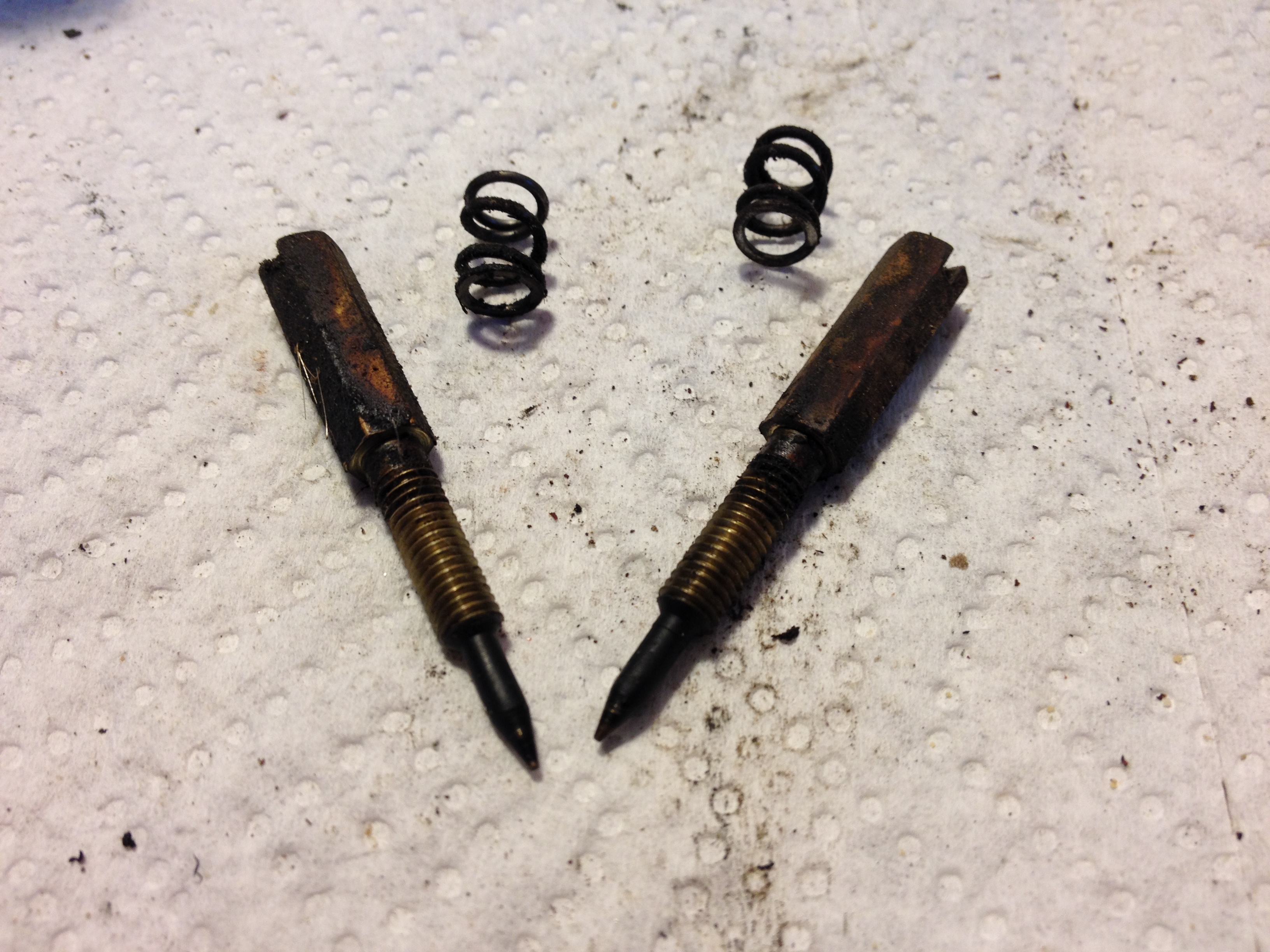
The throttle body is also the location of the two idle mixture screws. Simply back them all the way out, being careful not to lose the tension springs. The most important thing to know about idle mixture screws in general is that 1) you must not screw them all the way in with any force as you will damage them and possibly their seats in the throttle body casting; and 2) you can almost always get away with screwing them all the way in (gently!) and then backing them out about two turns as a starting point for setting the idle speed.
Below is a shot of the screws and the holes from which I've removed them.
Below is a shot of the screws and the holes from which I've removed them.
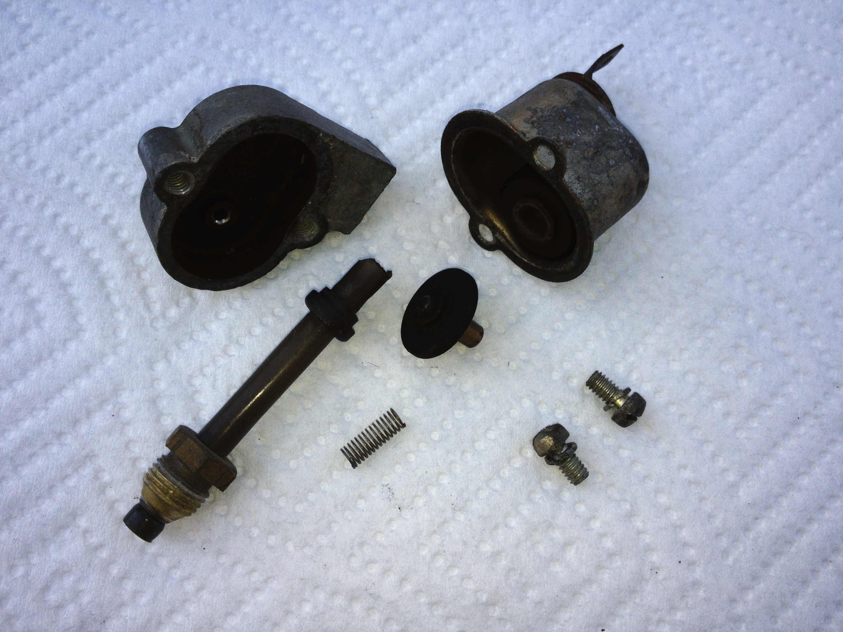
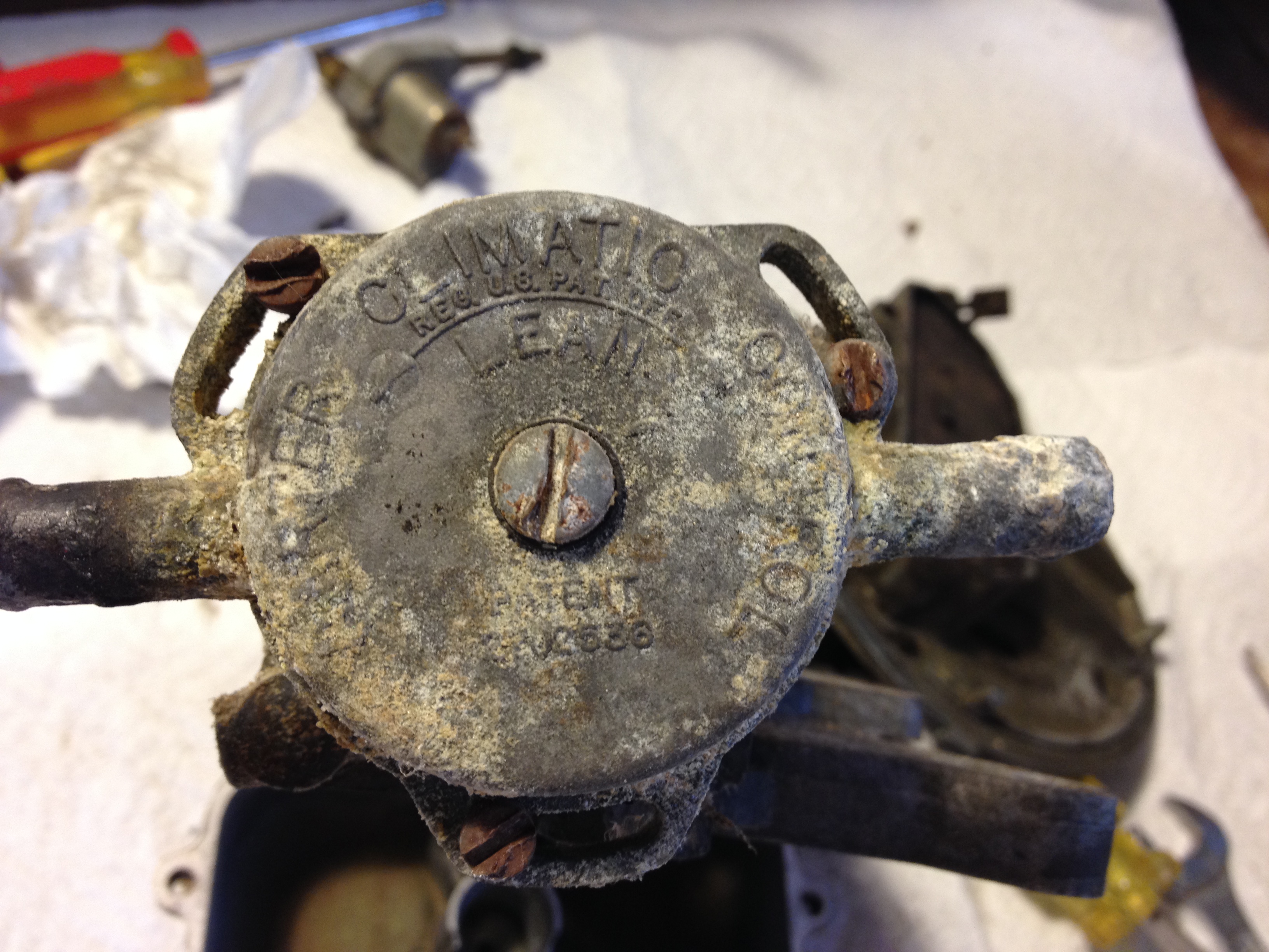
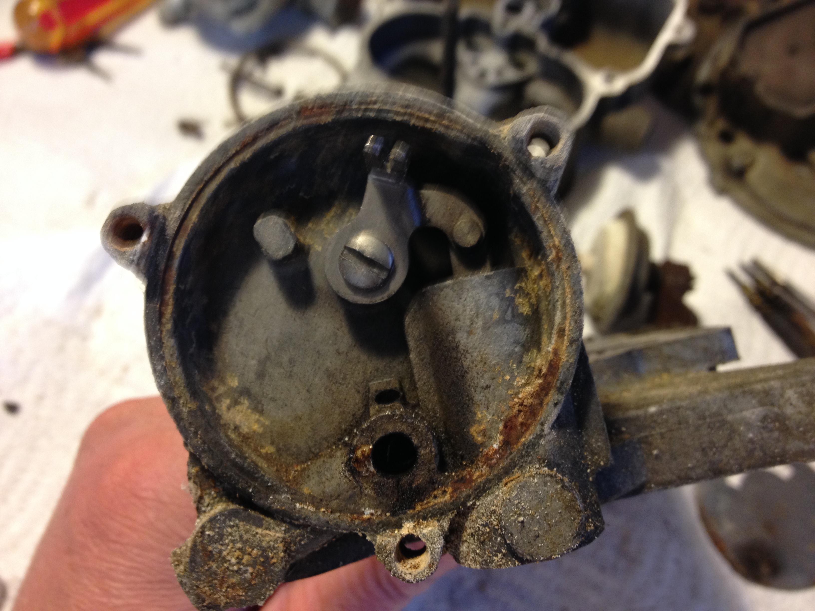
Finally, we have the choke. The wonderful "Carter Climatic Control" cooling system-controlled choke. It's an interesting idea, but one that clearly didn't work well since this approach was only used for a couple years by Lincoln (on the Continental anyway). The corrosion caused by the cooling system on the aluminum body of the choke is apparent in the picture below left. Coolant flows in and out of an outer chamber of the choke. Radiant heat then causes the bimetal spring attached to the inner side of the outer chamber to move, thus activating the choke plate. The spring mechanism is seen below right.
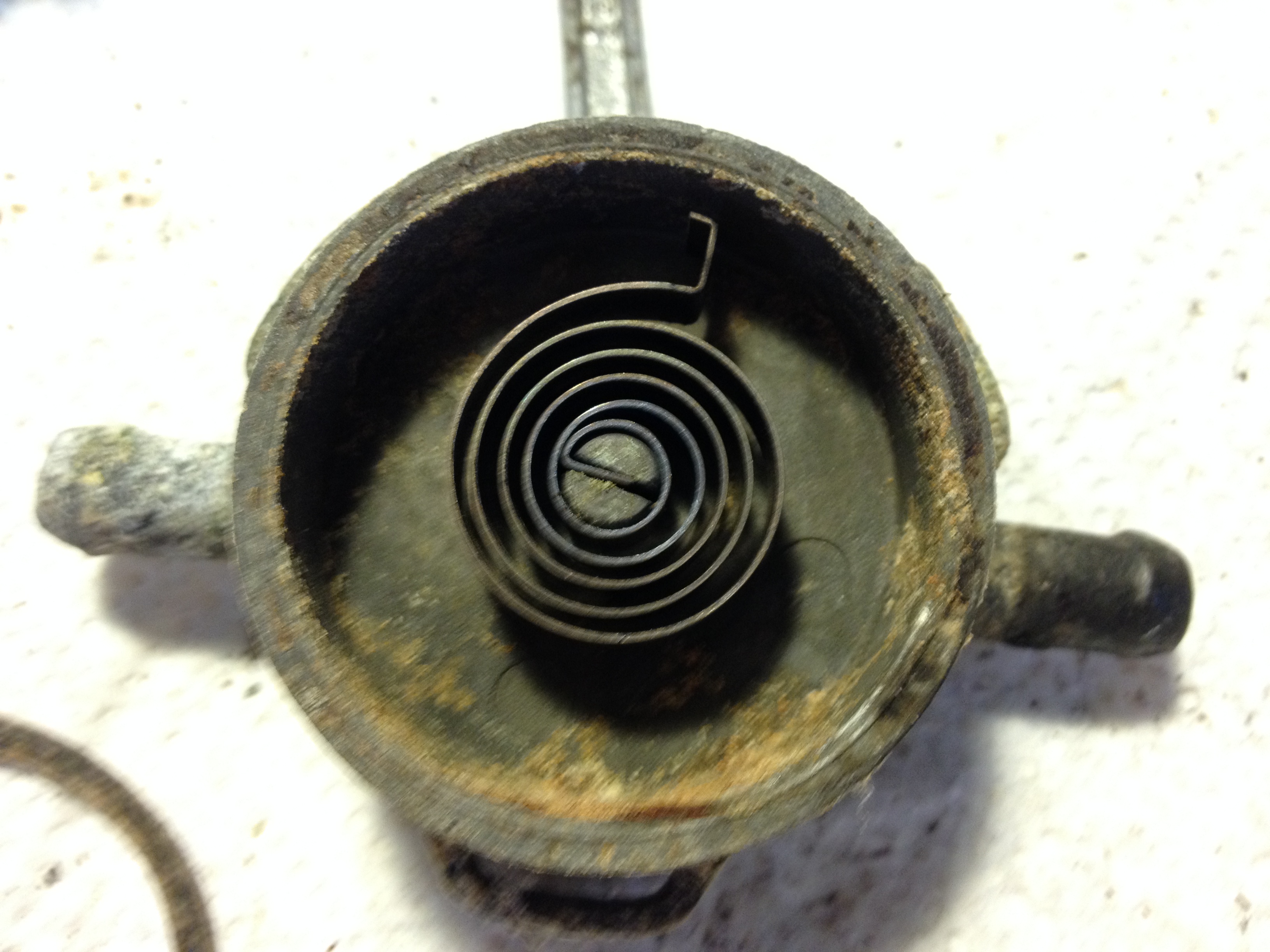
The spring operates on the choke linkage within the inner chamber (cast into the throttle body itself) to move the choke piston up or down which, in turn, moves the linkage to the choke plate open or closed. The choke piston is further acted upon by vacuum from the throttle body.
That's pretty much all there is to the tear-down of the Carter ABD. Next step is cleaning things up and reassembly!