My 1976 Jeep CJ-5
Find me on JeepForum
Carter ABD Carburetor Reassembly
Once everything was torn down to the component pieces, nearly everything went into the chem-dip for a good soaking. The only things I didn't clean this way were plastic parts or metal parts with plastic bits that couldn't be removed such as the housing for the idle speed-up control solenoid. After soaking everything was scrubbed with a brush, blown out with compressed air, and some things were hit with a Dremel sporting a brass wire wheel.
I then laid everything out ready for reassembly using the kit from Mike's.

Assembly happens pretty much in the reverse order of disassembly. There's nothing tricky about it but it certainly helps to have lots of pictures to go by—particularly when it comes to reattaching the various bits of linkage. Since most carbs usually have multiple options when it comes to which hole a bit of linkage should go in it can be difficult to remember what is correct for your particular application. Take many pictures before you tear things down! (I learned that lesson in high school many years ago…)
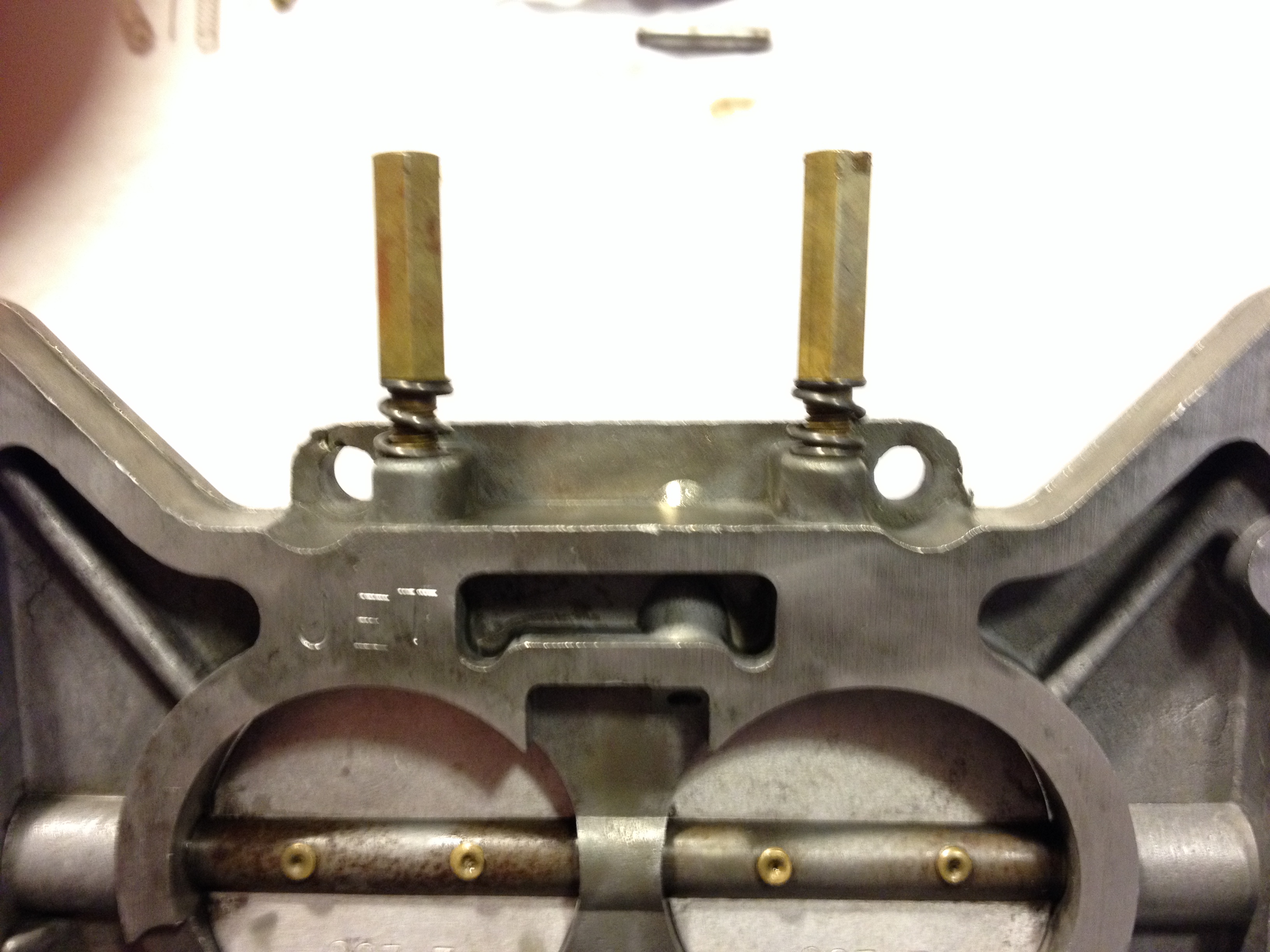
So, in go the idle adjustment screws. I gently screw them in until they are fully seated and then back them out two turns each. This will be a good starting point for setting the idle speed when the engine is running.
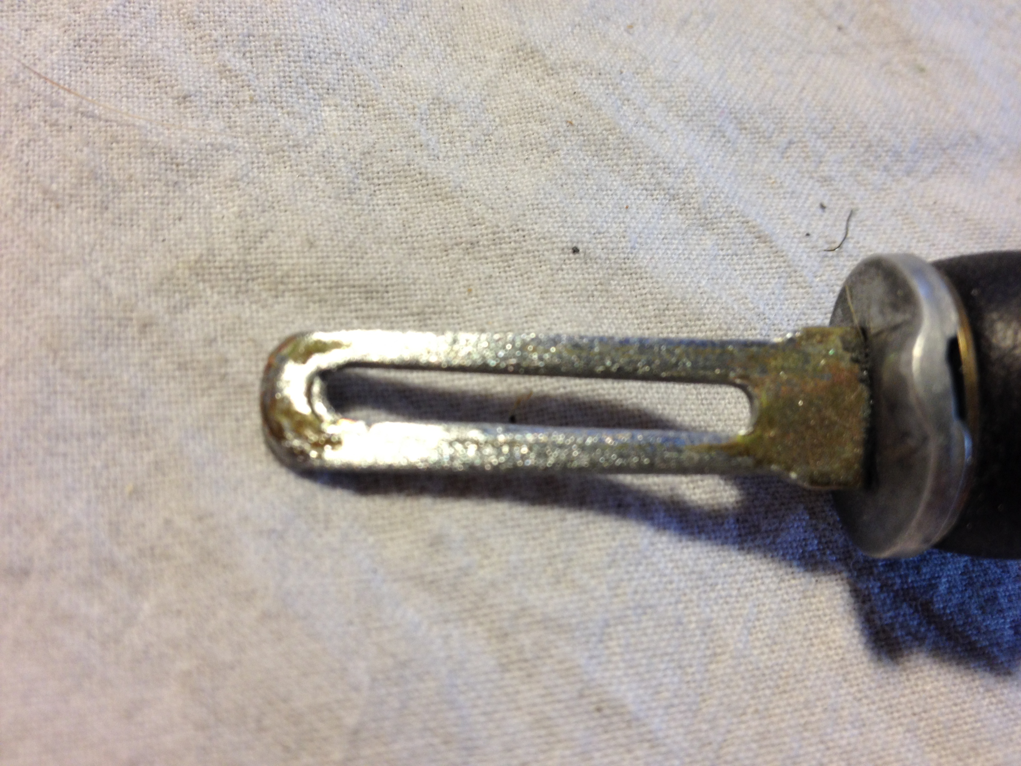
Next, it's time to reassemble the choke. I spent a bit of time working on the choke piston to free it from its frozen state, then working the linkage until everything was moving easily. To put it all back together the first thing is to lay the steel plate across the inner housing in such a way that the slot is aligned with the forked link that the bi-metal spring will fit into. Then on goes the gasket.
So, in go the idle adjustment screws. I gently screw them in until they are fully seated and then back them out two turns each. This will be a good starting point for setting the idle speed when the engine is running.
Next, it's time to reassemble the choke. I spent a bit of time working on the choke piston to free it from its frozen state, then working the linkage until everything was moving easily. To put it all back together the first thing is to lay the steel plate across the inner housing in such a way that the slot is aligned with the forked link that the bi-metal spring will fit into. Then on goes the gasket.

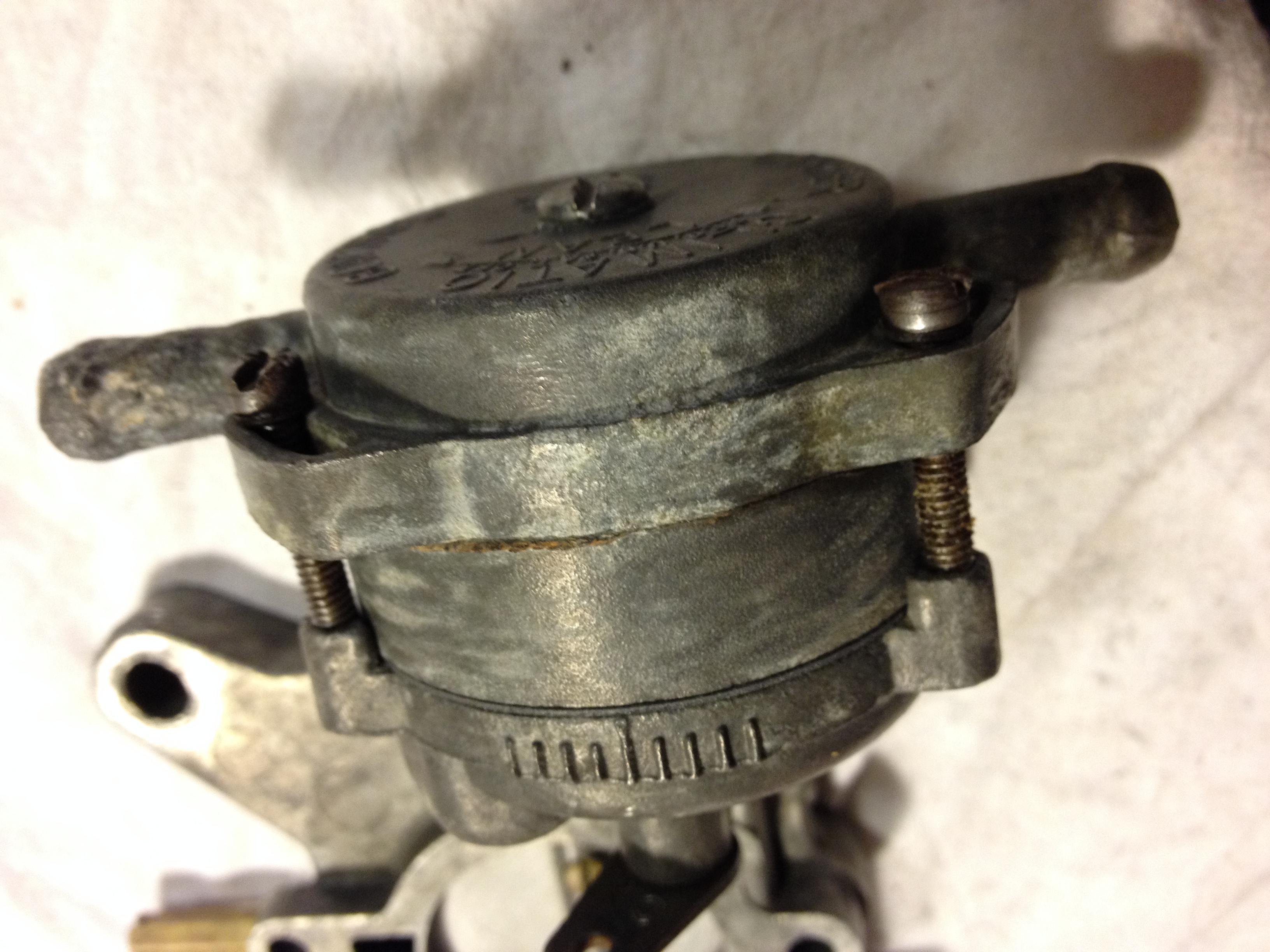
The next step is to carefully align the spring with that forked linkage as you place the outer housing onto the inner housing. While holding the pieces together you should now be able to move the linkage and feel the tension from the spring sealed inside. If things look good tighten the screws. In my case, I set the choke to the same position it was in before I disassembled things. Though the inner housing has alignment marks for setting the choke, the outer housing has none. Strange.
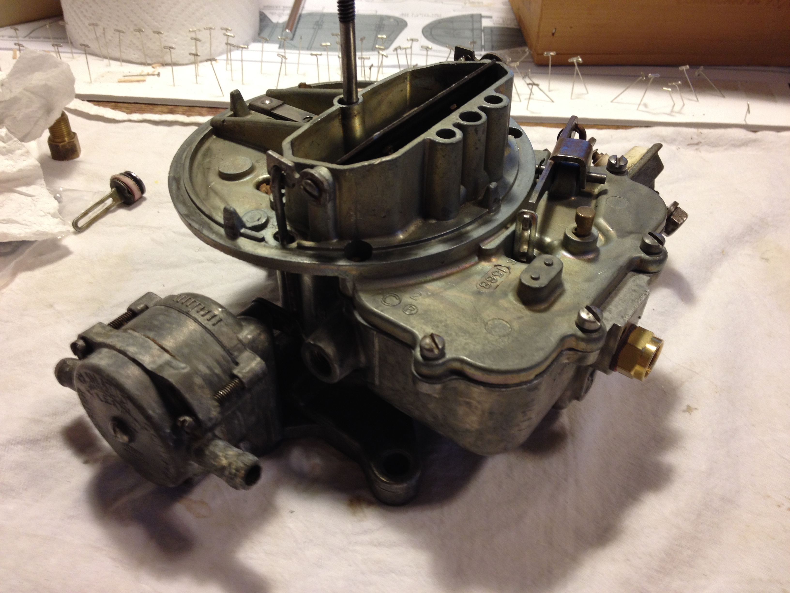
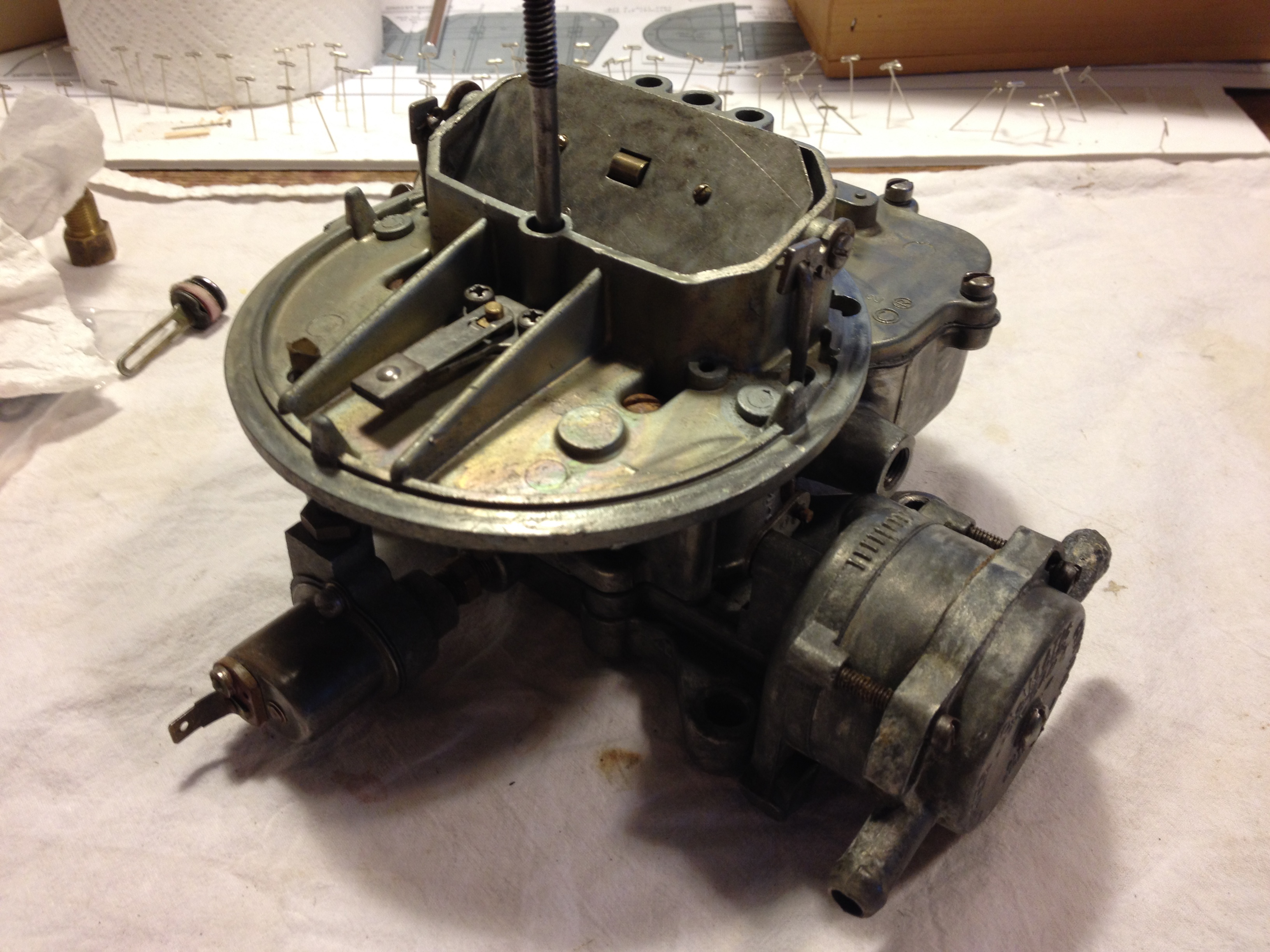
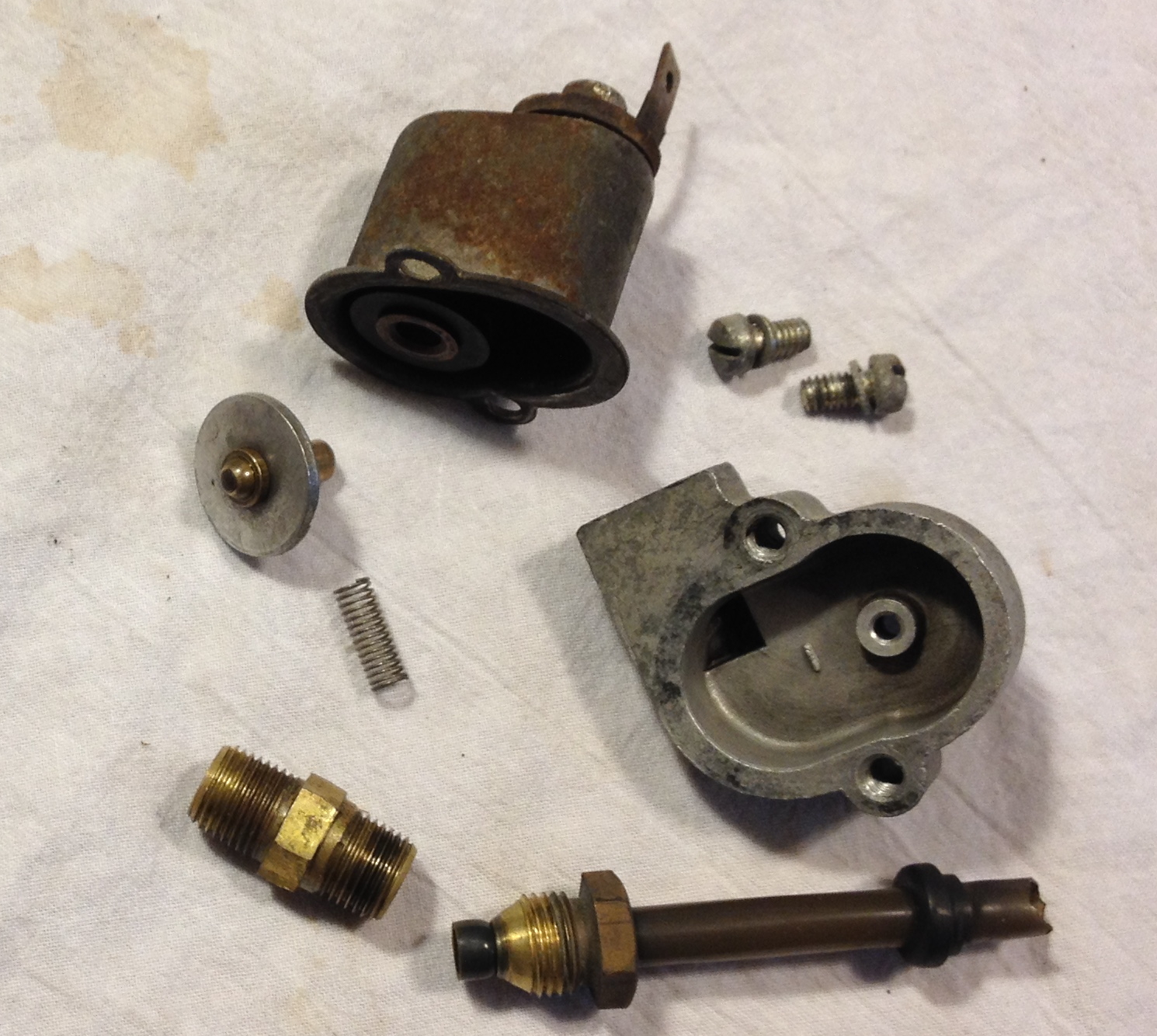
The last part of the throttle body assembly is putting the idle speed-up control assembly back together and reattaching it. After cleaning the parts I first tested the solenoid by inserting the spring and the valve into the solenoid as it would normally go—the spring holds the valve away from the solenoid windings, a position that causes it to plug the hole through which air flows from the air cleaner assembly directly into the manifold bypassing the carburetor proper. Applying 12 volts to the solenoid confirmed that it immediately retracted the valve into the solenoid windings. Stopping the voltage allowed the spring to push the valve out again. When the air conditioner kicks in, it sends an electrical signal to the solenoid, allowing a shot of air in to the manifold and slightly increasing idle speed to compensate for the extra load on the engine. In the picture below I hadn't yet cleaned the solenoid assembly (one of those bits that didn't go in the chem-dip).
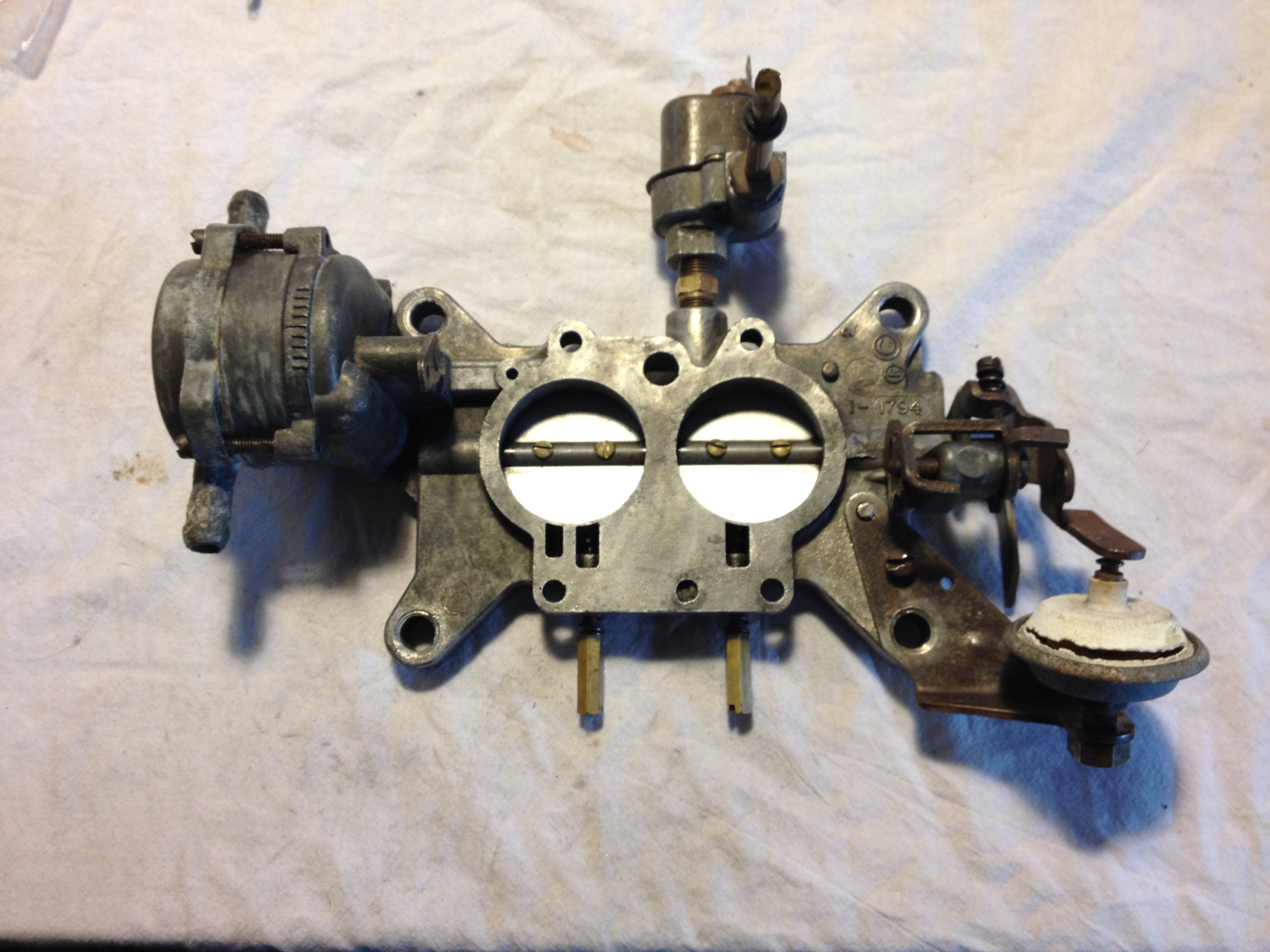
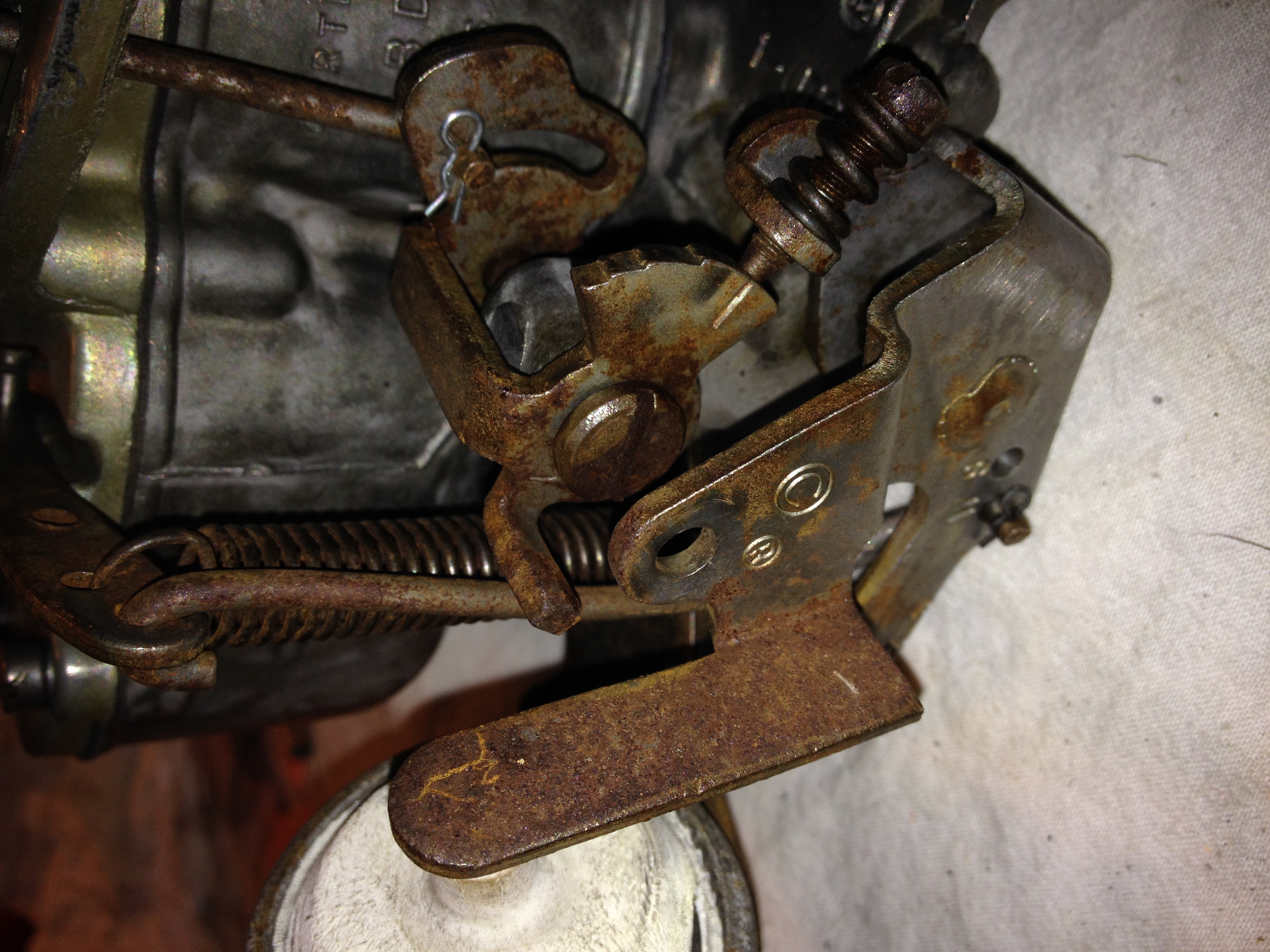
Here's the completed throttle body assembly ready for the float bowl to be attached. Note the cracked dashpot. I reinstalled the bad one while searching for a replacement. The old one pretty much fell apart as I was disassembling things and it clearly hadn't worked in years.
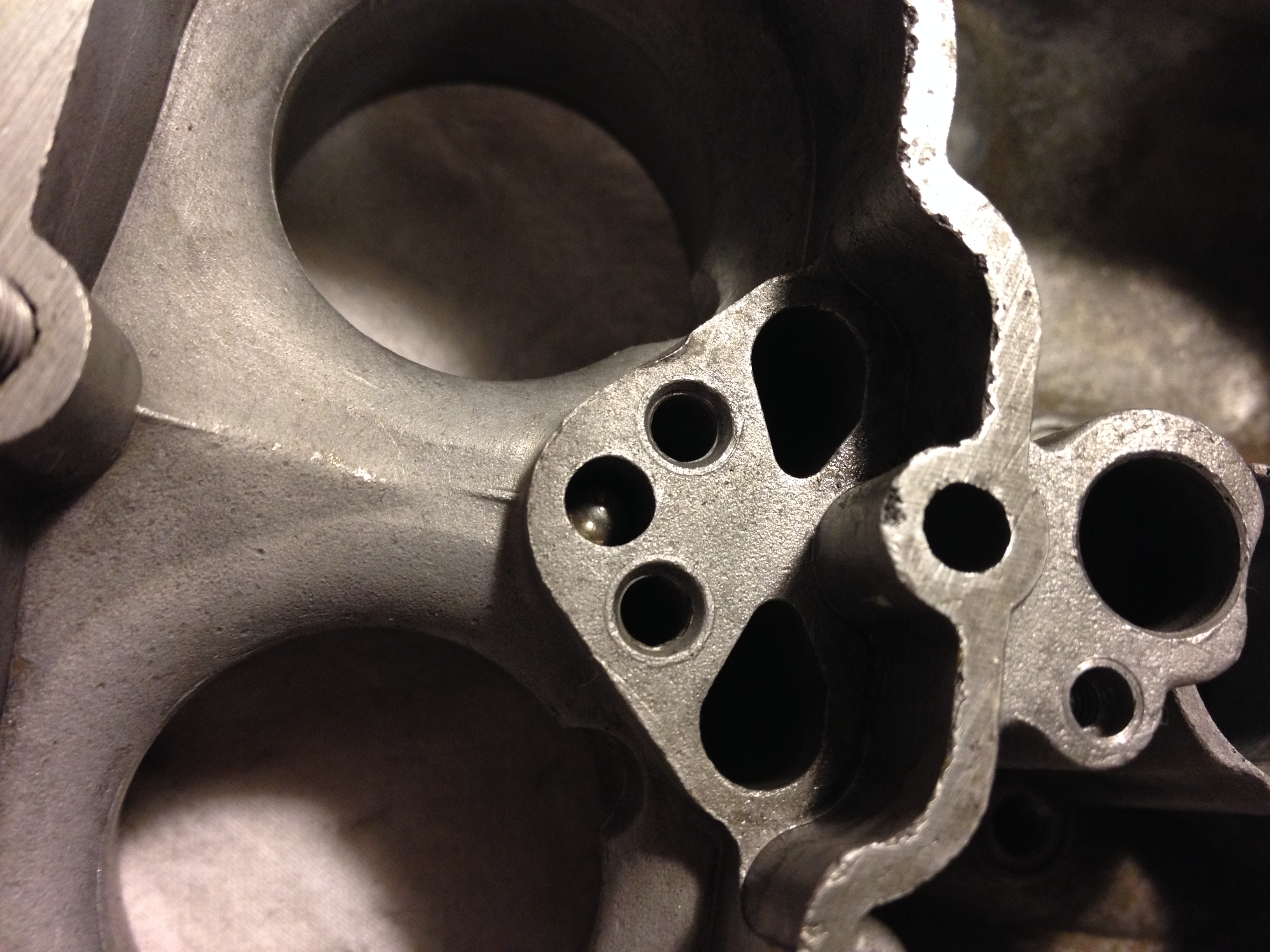
Moving on to the float bowl assembly the first order of business is inserting one of the check balls beneath the booster venturi assembly. The rebuild kit included two check balls, however one of them was aluminum rather than steel and I opted not to use that one—re-using the original ball instead. Then the venturi gasket was put in place and the venturi seated and the two pump discharge screws replaced. I didn't spend enough time on the screws removing the rusty spots. Grrrr...
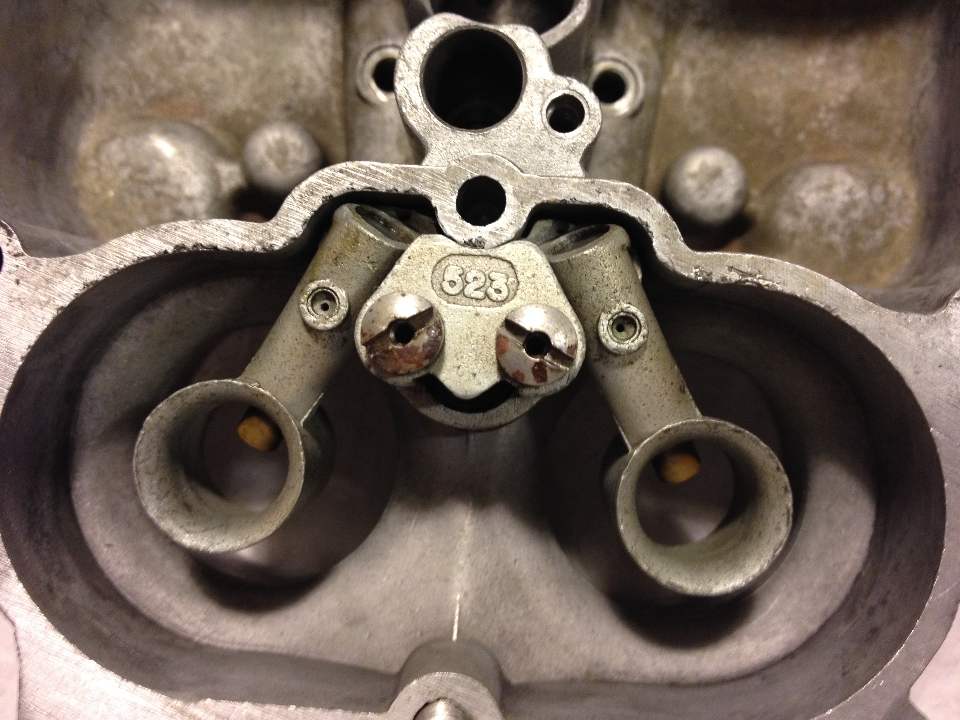
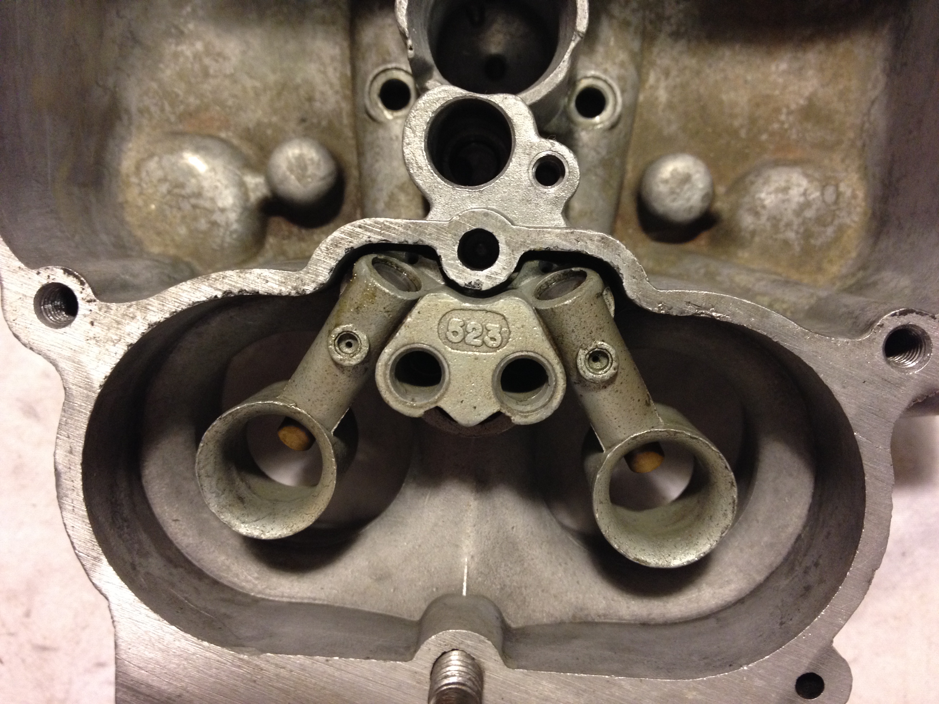
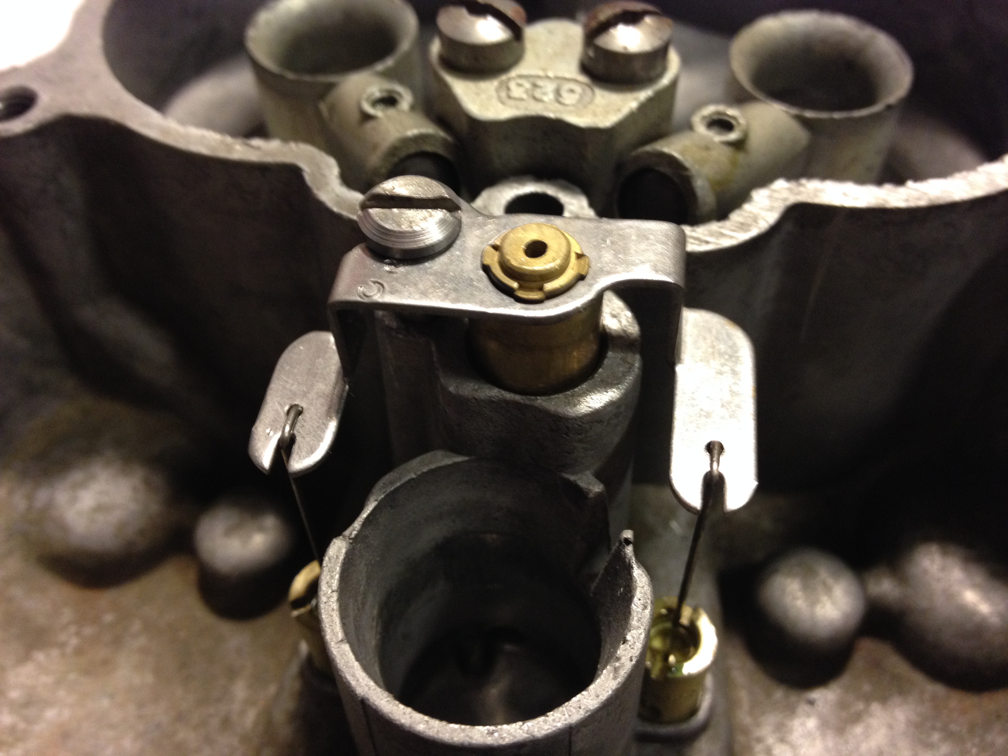
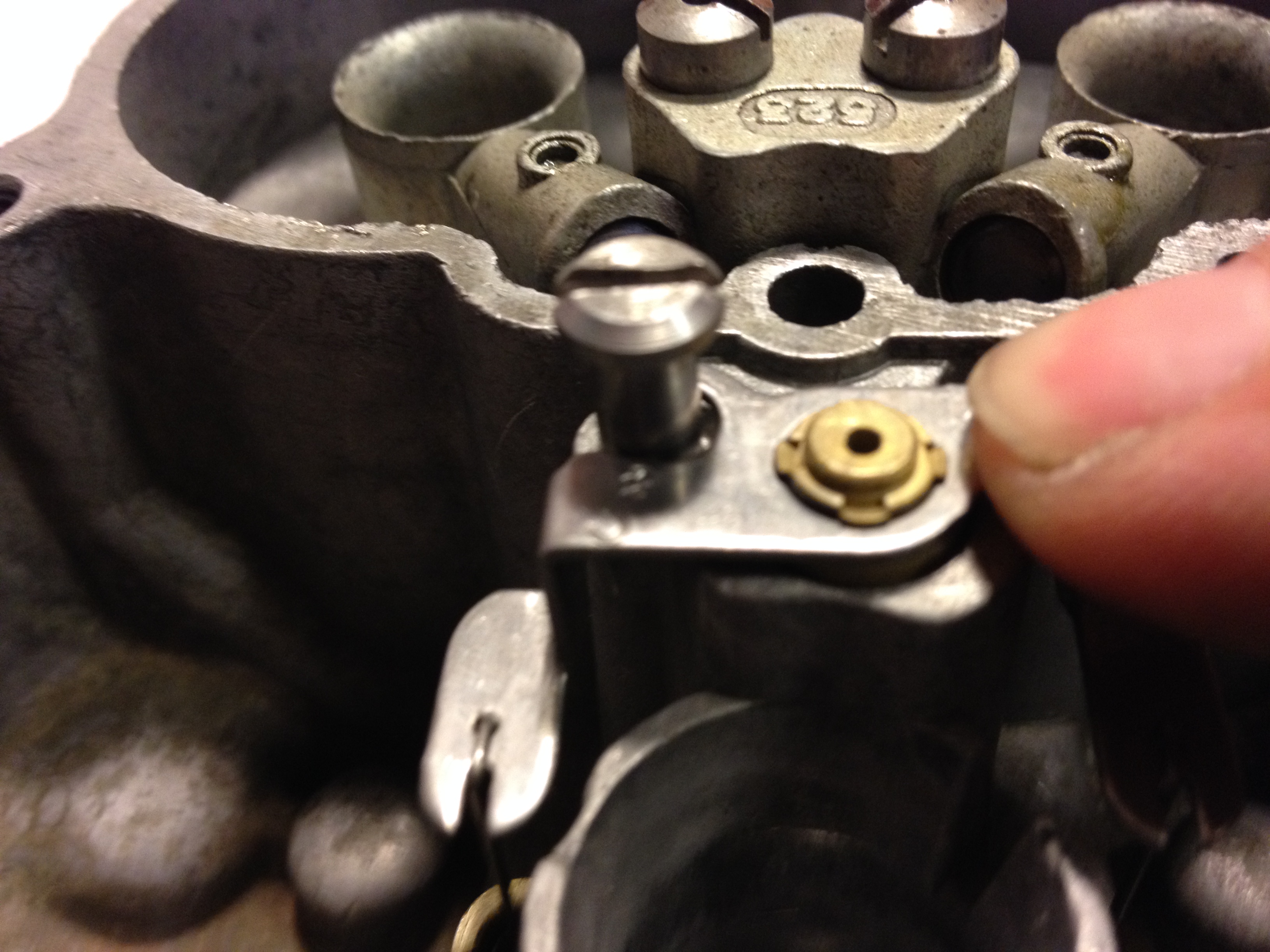
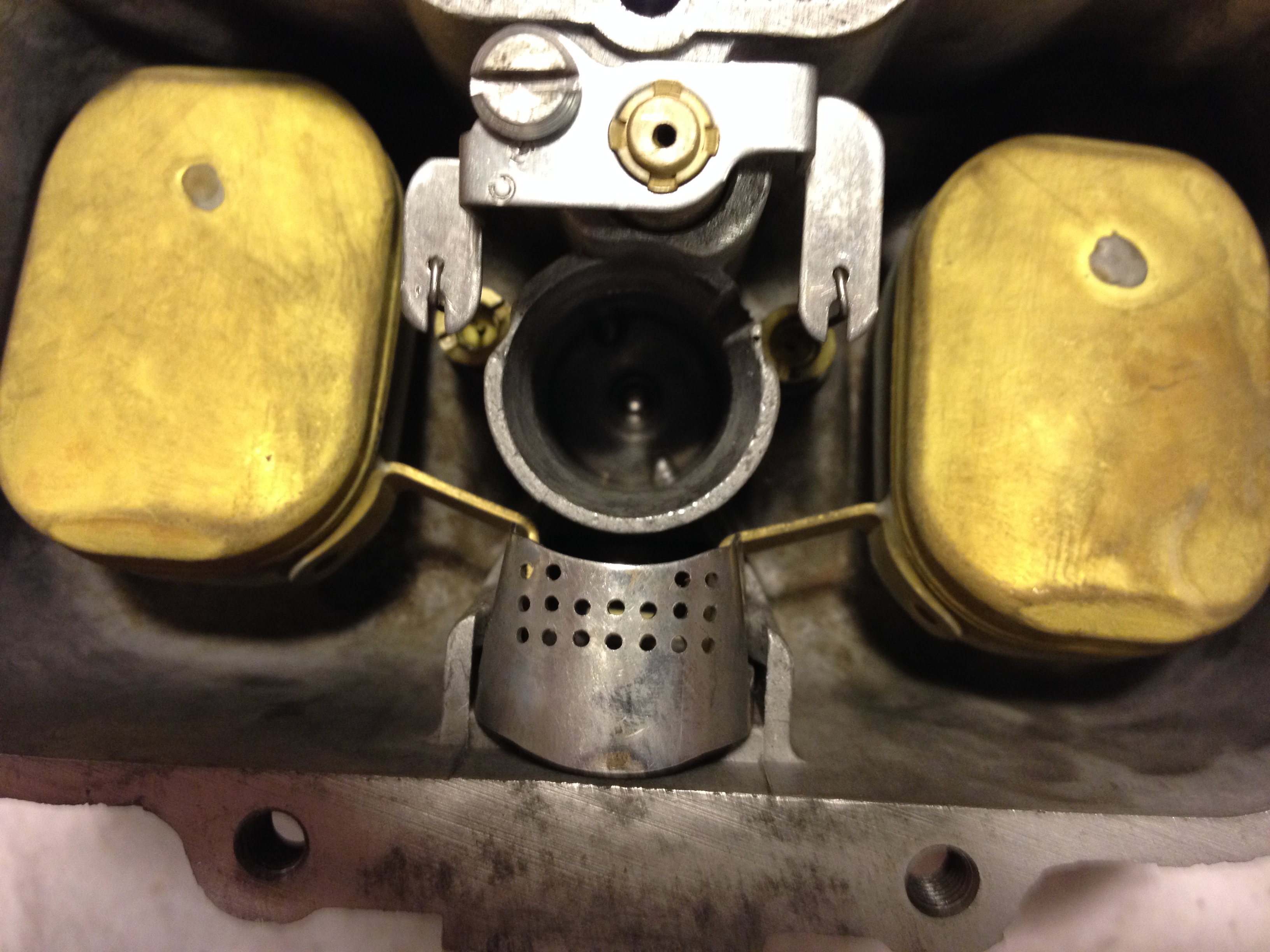
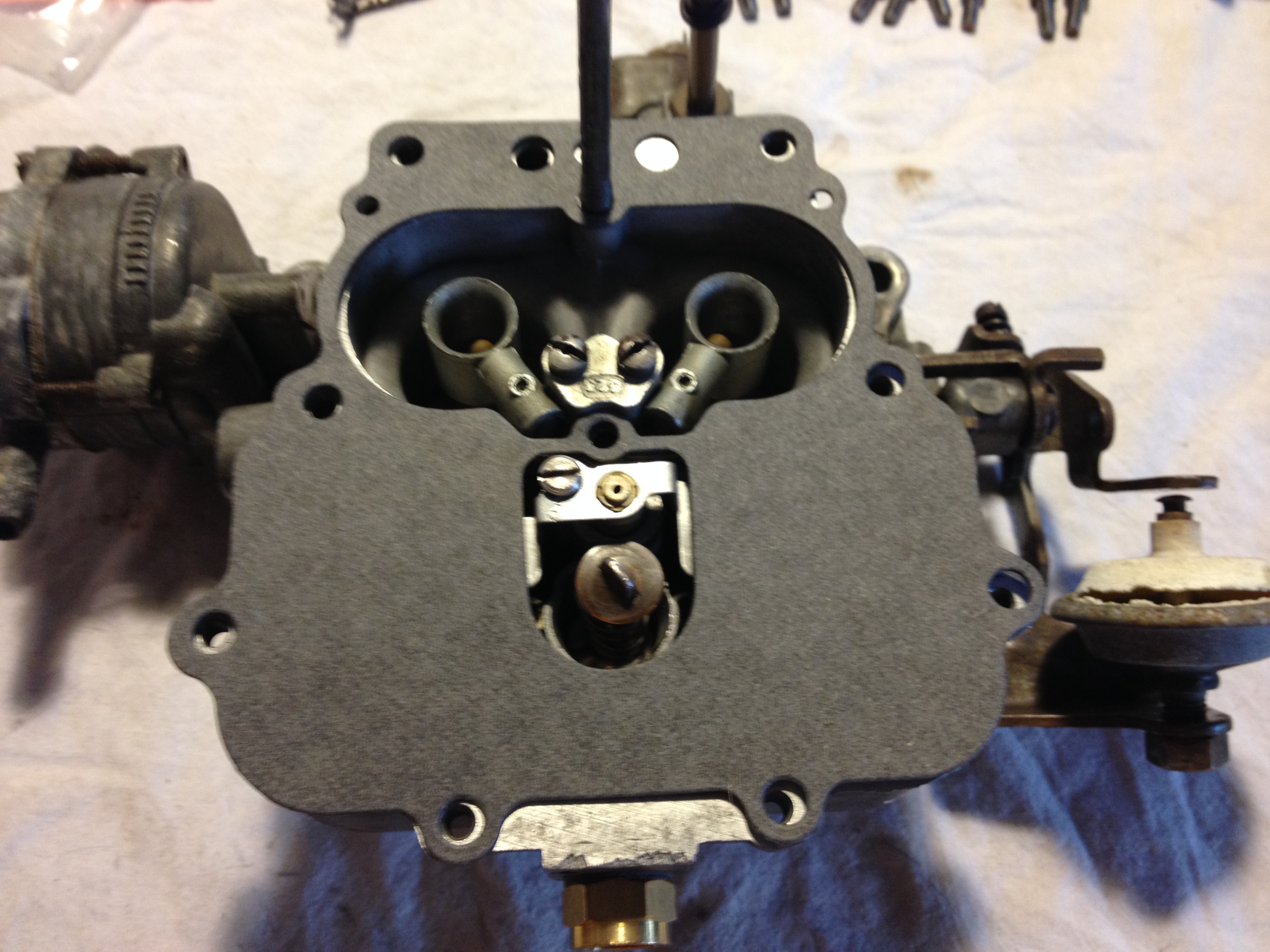
Next comes the vacuum metering system. First the main jets go in, then the metering system. There's a gasket that goes down the hole (missing when I tore the carb down) and one must be careful when putting things together so that the metering rods aren't bent. The whole thing sits in the hole and is held in place by a screw such that it moves freely up and down. Idle-speed vacuum will pull it down into the hole—seating the metering rods in the jets and blocking fuel flow (in the picture lower right my finger is pretending to be vacuum). As the engine revs vacuum disappears and the systems rises out of the hole (pushed up by the spring to the extent allowed by the retaining screw), pulling the metering rods out of the jets. Simple!
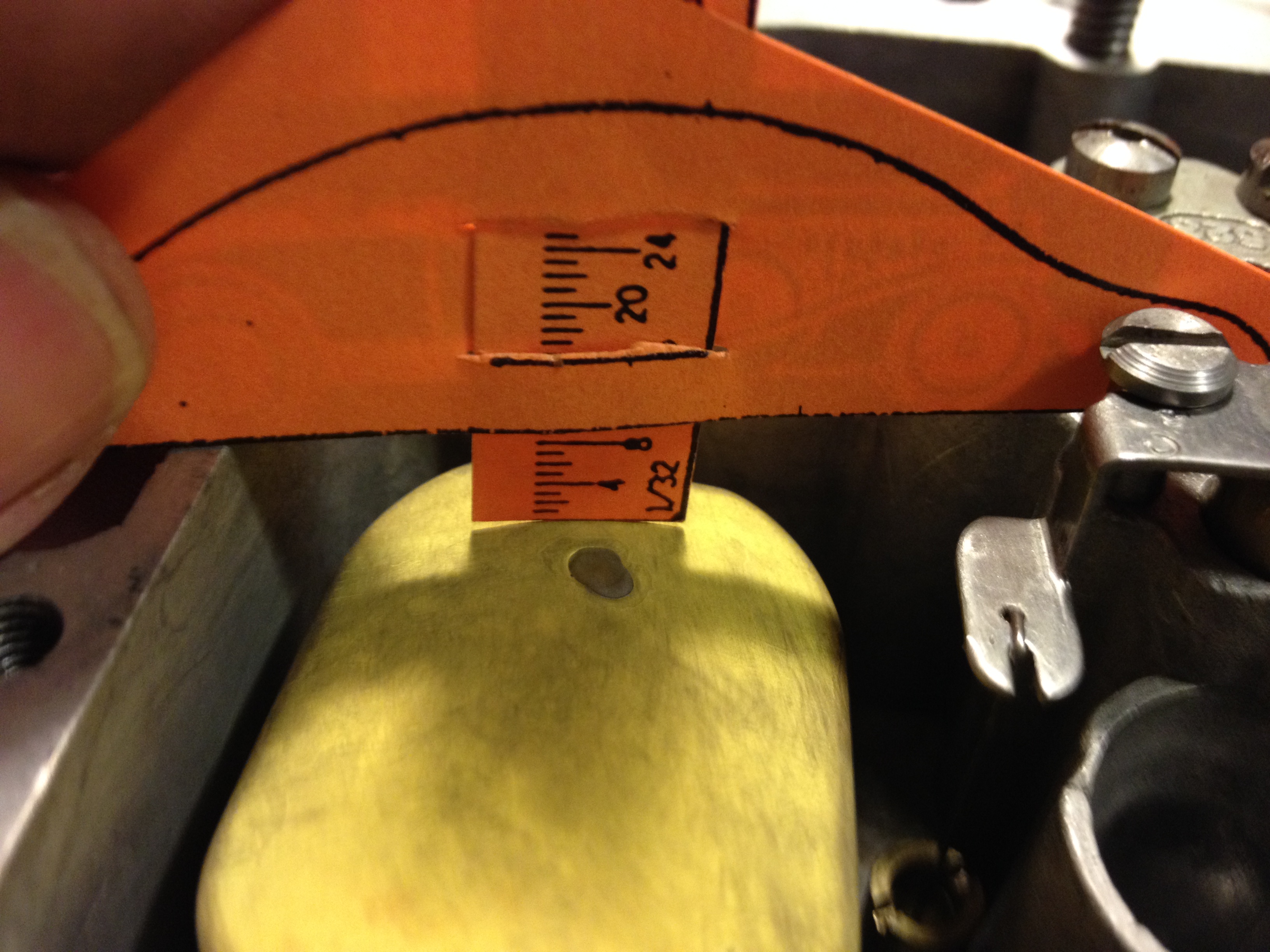
Now comes the fun part: the fuel inlet needle and floats. The rebuild kit included a replacement for both the needle and the housing/fitting the incoming fuel line screws into. First the floats and their pivot pin are placed in the bowl, then the inlet and needle are screwed in to the float bowl (using the provided gasket). Before inserting the retaining clip that keeps the floats and retaining pin from coming loose, the floats must be adjusted as per the instructions. The rebuild kit comes with a paper ruler that allows one to reference the top of the float bowl to ensure a distance from that point down to the top of the floats. This should be 5/16" (meaning the tops of the floats are essentially parallel to the top of the float bowl when they are floating on the fuel in the bowl). There's a tab in the middle of the float assembly that rests against the inlet needle—preventing it from falling into the float bowl and also pushing the needle into its seat as the fuel level rises in the bowl, effectively turning off the flow of incoming fuel. This tab must be gently bent until the appropriate distance is set. A bit of trial and error to get it right, but no big deal.
Below left is the old inlet fitting and needle (top) and the new replacements (bottom).
Below left is the old inlet fitting and needle (top) and the new replacements (bottom).


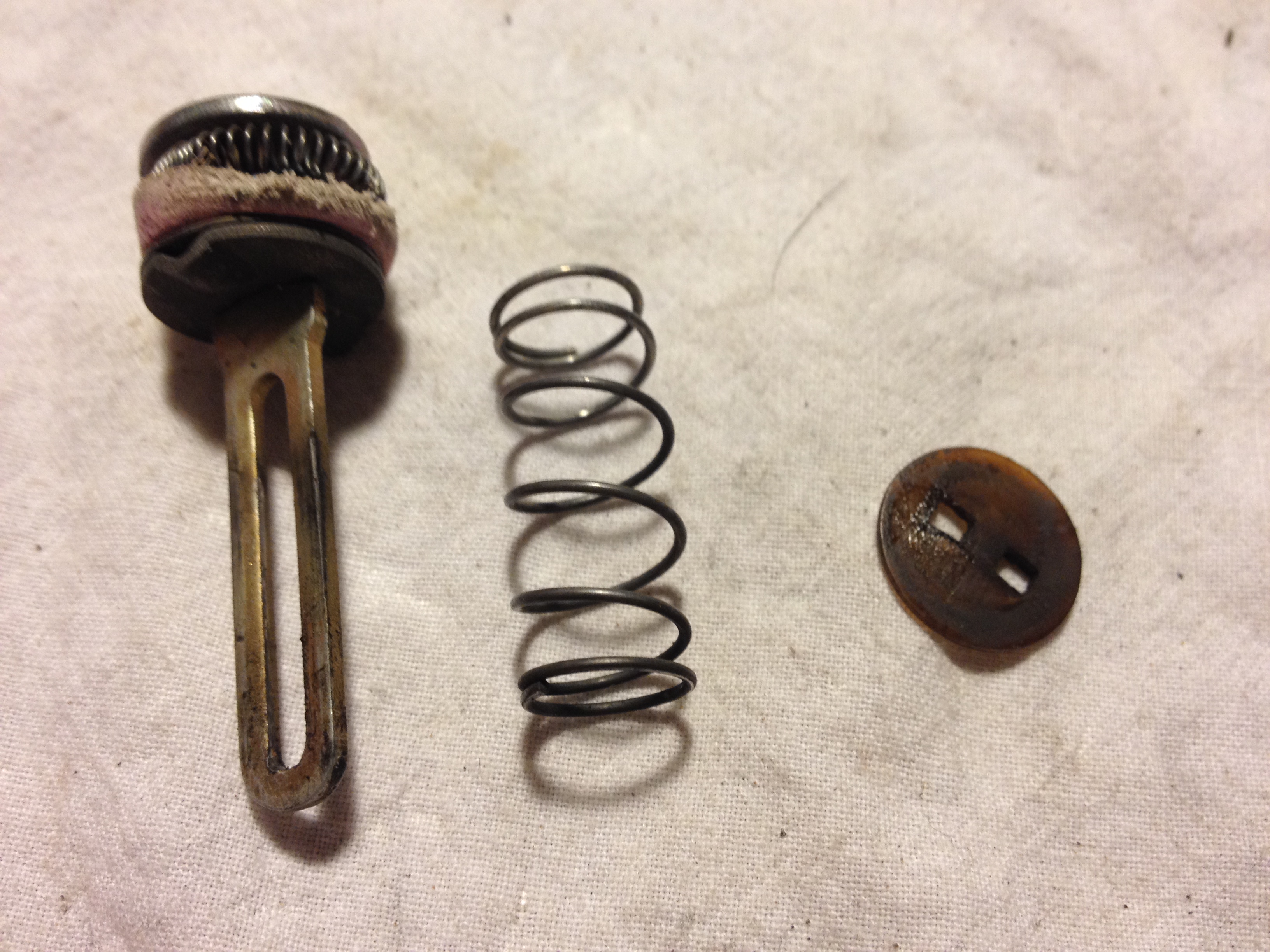
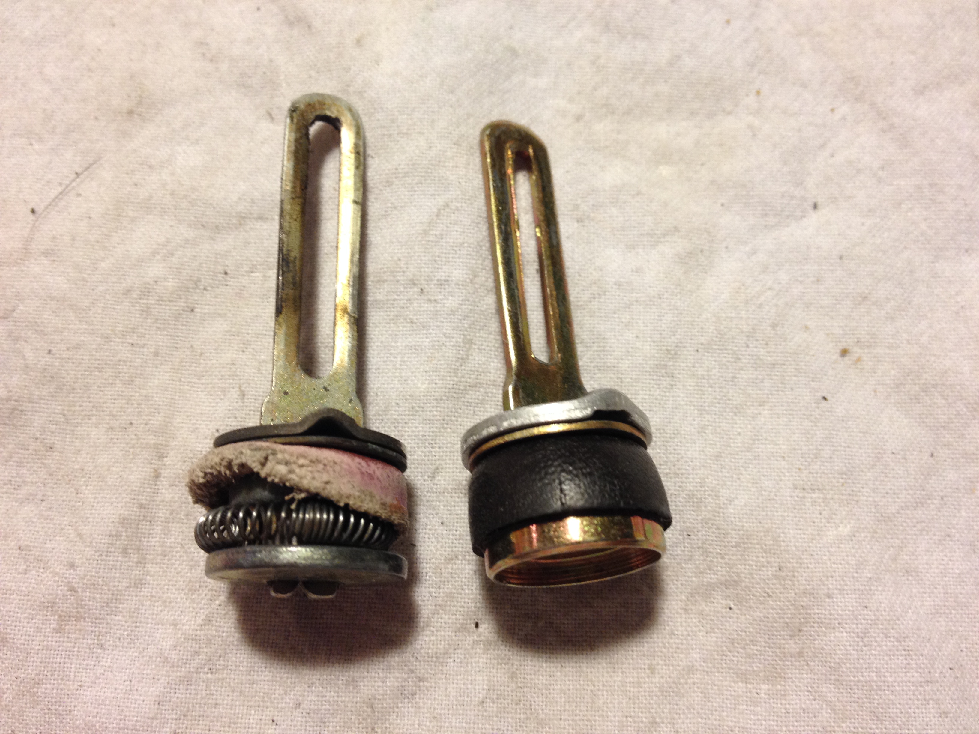
Finally, the accelerator pump is installed. I had a bit of a challenge with this, not because assembly is difficult but because the quality of the replacement part left something to be desired. Here is the old pump disassembled and a side-by-side shot of the old pump and the new one. Note the quality of the stamping on the new one. All those rough edges and lack of parallel lines meant the retaining disk holding the spring on to the pump wouldn't move freely at all.
I spent a good bit of time with the Dremel and a grinding wheel working on the pump to get it to the point where the retaining disk would move freely. I hate to say it, but I'm guessing Made in China...
Here's the cleaned up retaining disk—some sort of plastic that I was worried might break with all the installing and removing to get things right. And the finished pump before I installed the spring and disk. Once it was assembled I let it soak for a bit in kerosene to allow the gasket to swell. Before placing it in its well the second check ball from the rebuild kit was dropped into place. The way the bowl is cast the ball goes right where it should.
Here's the cleaned up retaining disk—some sort of plastic that I was worried might break with all the installing and removing to get things right. And the finished pump before I installed the spring and disk. Once it was assembled I let it soak for a bit in kerosene to allow the gasket to swell. Before placing it in its well the second check ball from the rebuild kit was dropped into place. The way the bowl is cast the ball goes right where it should.

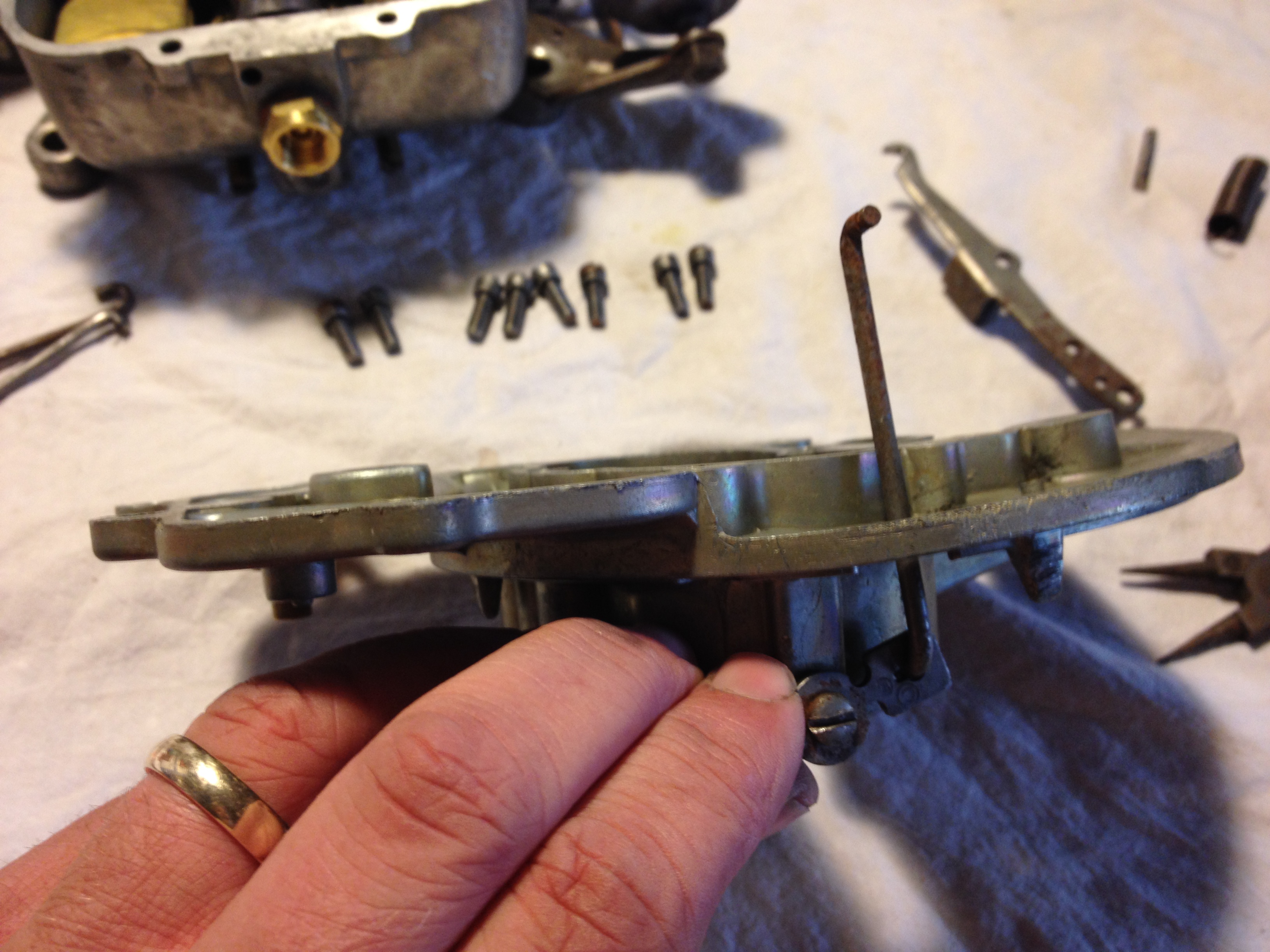
At this point the float bowl is complete and ready for the gasket between it and the air horn. So on they go. This is also the point at which the first bit of linkage is reattached. The choke valve must be linked to the choke as the air horn is lowered into place.
It was also at this point that I discovered something interesting. The air horn is bent! It must've been when I tore things down but I didn't notice it then. One corner is a good 1/8" lower than the rest. Fortunately, it's at a position where this doesn't seem to impact things. When the air horn is in place and the eight screws driven in it seems to seat completely against the gasket. If it didn't it would cause not only a huge vacuum leak but fuel would be allowed to simply slop out of the bowl!
It was also at this point that I discovered something interesting. The air horn is bent! It must've been when I tore things down but I didn't notice it then. One corner is a good 1/8" lower than the rest. Fortunately, it's at a position where this doesn't seem to impact things. When the air horn is in place and the eight screws driven in it seems to seat completely against the gasket. If it didn't it would cause not only a huge vacuum leak but fuel would be allowed to simply slop out of the bowl!
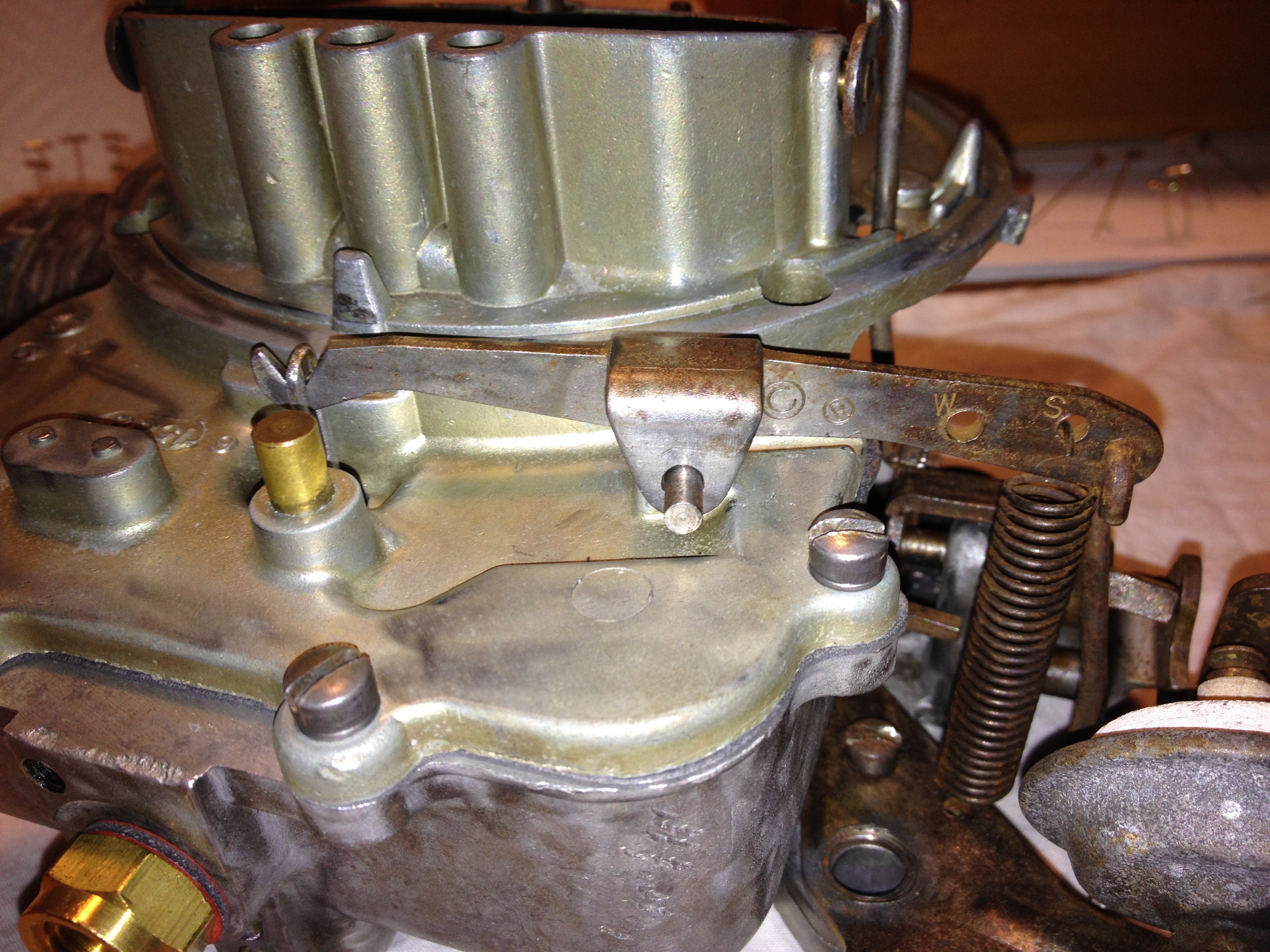
Once the top has been screwed into place and the choke linkage reattached the last steps are to reinstall the hot idle compensator and the accelerator pump arm. This last piece hooks into the accelerator pump which sticks up through the top of the air horn and is also attached to the accelerator linkage by another connecting rod. There's also a tensioning spring which connects the arm to the plate onto which the dashpot is mounted. Finally, the linkage between the choke plate and the fast-idle cam needs to be replaced. All pretty straight-forward—assuming you took pictures and can get the various links back into the appropriate holes.
That's pretty much all there is to it. The only remaining things to do are to ensure that adjustments are made according to the rebuild kit instructions. These might entail bending the linkages to ensure proper clearances for the choke and throttle plates, the dashpot location, etc. Once the carb is back on the engine idle adjustments and mixture setting can be done.